Electrochemical system and method for the treatment of water and wastewater

a technology of electrochemical treatment and wastewater treatment, applied in the field of water and wastewater treatment, can solve the problems of prior art efforts to improve systems and electrochemical treatment methods for wastewater treatment, widespread use of chlorine, and elimination of disinfection

Active Publication Date: 2009-12-31
ELECTRO CHEM CORP
View PDF15 Cites 39 Cited by
  • Summary
  • Abstract
  • Description
  • Claims
  • Application Information

AI Technical Summary

Benefits of technology

[0040]The systems and methods described herein take advantage of selective electrode materials which offer advantages one over the other for the removal of a specific contaminant or a combination of contaminants that may be present in an aqueous stream, or to achieve a specific byproduct chemistry based on either the further intended treatment steps or the ultimate fate of the byproducts of which are to be disposed. Selective electrode materials may include, but are not limited to, iron, aluminum, titanium, carbon fiber, stainless steel or any other effective electrode material.
[0041]The systems and methods described herein utilize specific electrode materials and configuration selection designed to achieve specific levels of treatment based on the specific contaminant or a combination of

Problems solved by technology

In the past chlorine was commonly used for the disinfection of both water and wastewater, but as a result of recognition by the US EPA that byproducts of chlorine may be potentially carcinogenic, new regulations have been passed limiting the widespread use of chlorine and requiring the reduction or elimination of disinfection byproducts.
Prior art attempts to improve systems and electrochemical treatment methods for wastewater treatment have not been satisfactory.
This typically results in rapid plugging or clogging of the treatment unit.
In the case of a single rod within a cylinder, often the spacing between the central rod and the perimeter wall is so great as to be ineffective in creating a sufficiently strong charge density to completely treat water or wastewater.
Due to the inefficiency

Method used


Image

  • Electrochemical system and method for the treatment of water and wastewater
  • Electrochemical system and method for the treatment of water and wastewater
  • Electrochemical system and method for the treatment of water and wastewater

Examples


second embodiment

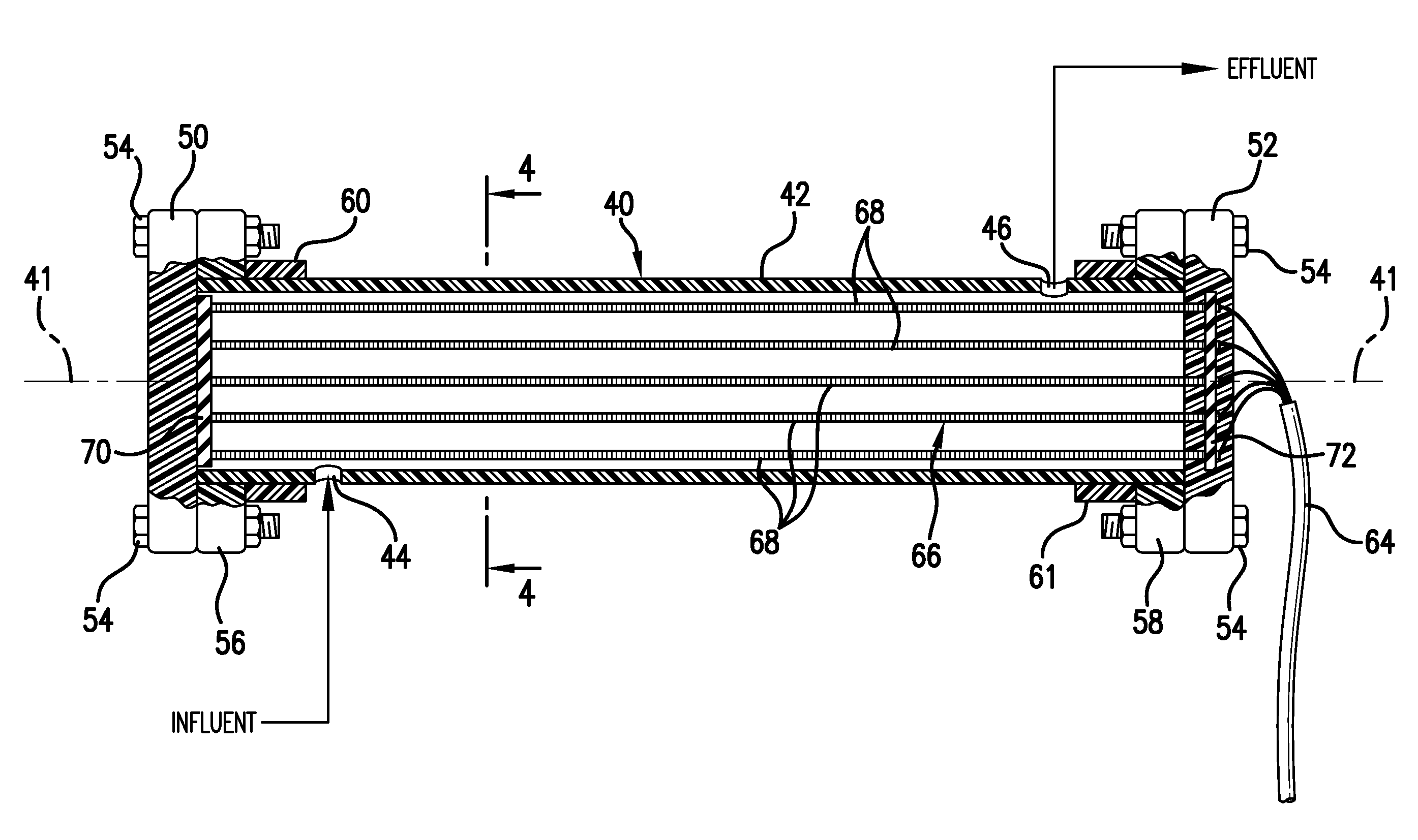
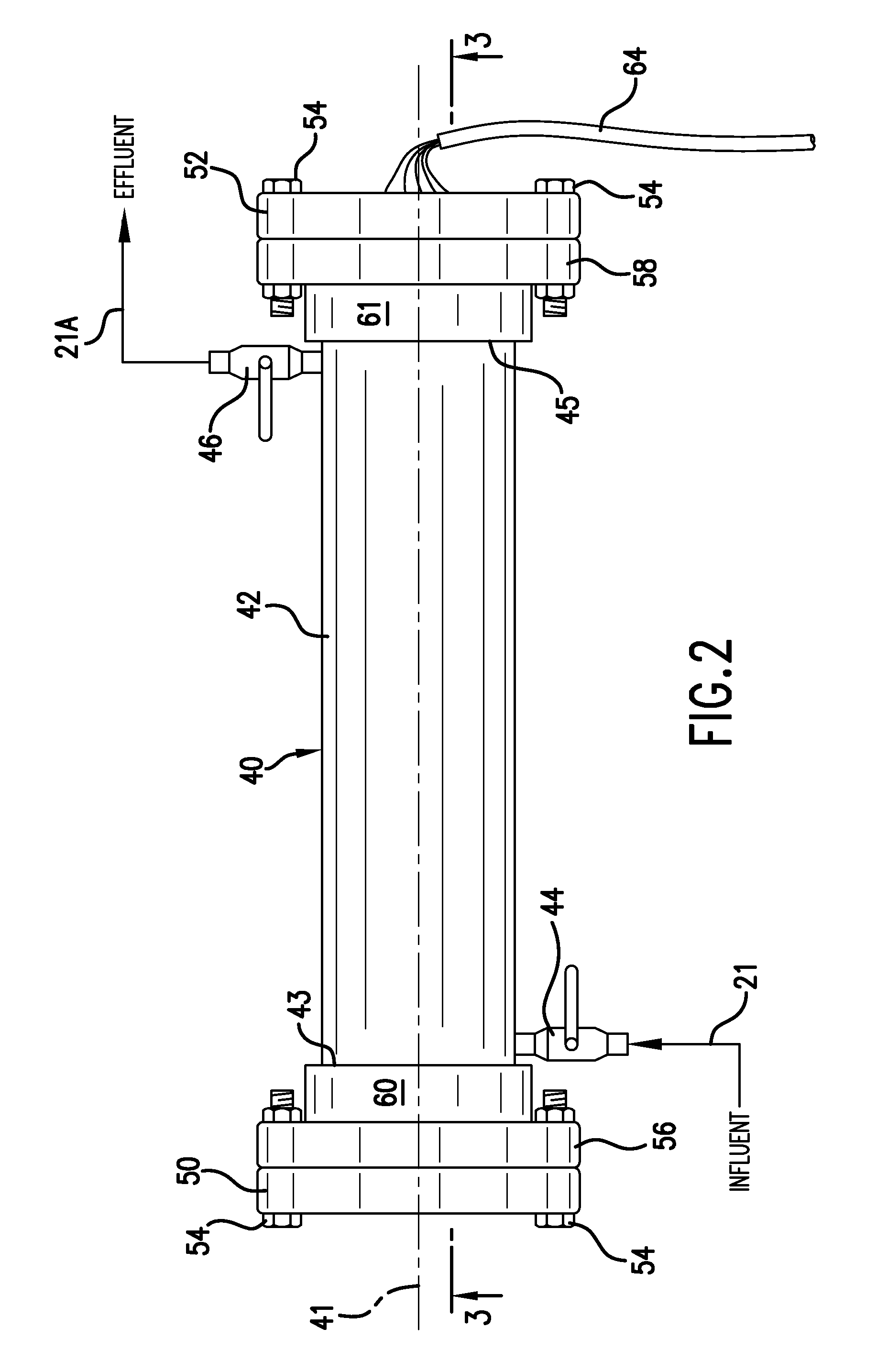
[0095]While the module 40 is shown aligned with a horizontal axis in FIG. 2, the module 40 is oriented with a vertical axis 41′ in the invention shown in FIG. 7. This takes advantage of the tendency of gas to flow upwardly allowing gas to vent via a vent 34 now disposed proximate the upper end 43 of the chamber 42 of the module 40.

[0096]The key to successful electrochemical treatment of waste and raw water at atomic and molecular levels is effective application of voltage, amperage, hydraulic retention time and electrode material in combination to provide electrical charge densities on the electrodes and electrical potential between the electrodes to produce a desired electrochemical reaction.

[0097]The following Charts A, B and C cite test data from testing the prototype illustrated in FIGS. 2-7 of the drawings. The parameters used occur within testing ranges initially selected by the inventor, which ranges do not limit the scope of the inventor's invention. The test data establish ...

third embodiment

[0123]Referring now to FIGS. 13-19 there is shown a third embodiment, electrochemical module 200. Referring now specifically to FIGS. 13 and 14, FIG. 13 shows a circular housing 202, while FIG. 14 shows an array of electrodes 204 which are inserted into the housing 202 in order to complete each of the assembled electrochemical modules 200 shown in FIGS. 17-19.

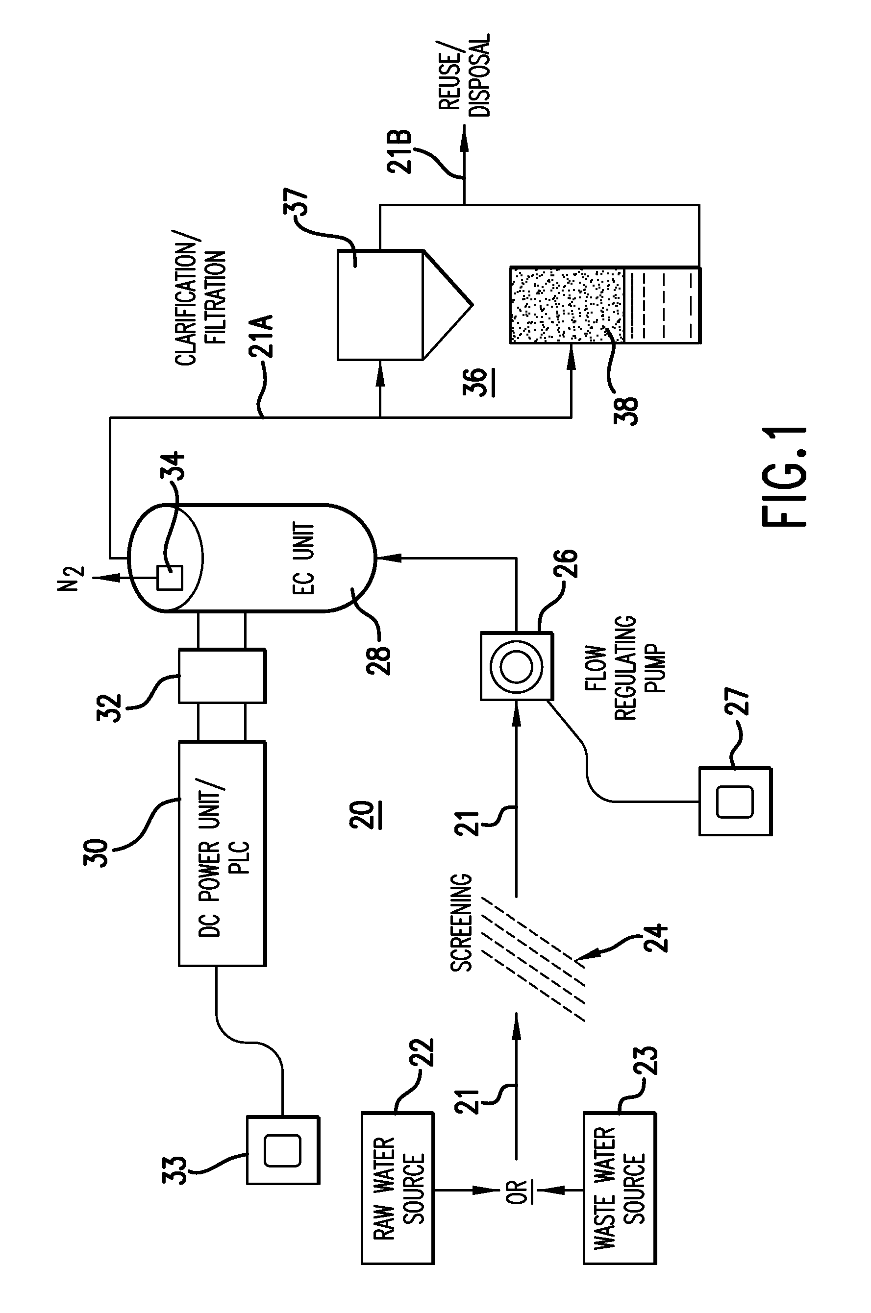
[0124]The housing 202 of FIG. 13 is made of a dielectric material such as polyvinylchloride (PVC) or of Fiberglass and includes a barrel portion 206 that receives the electrode array 204 and inlet 208 that receives contaminated water 21 (see FIG. 1) that is to be treated by the electrode array 204. The water 21 treated within the barrel exits through an outlet 210 for further treatment by the clarification / filtration station 36 (see FIG. 1).

[0125]The completed module 200 is formed upon placing an O-ring seal 202; at the upper end 214 of the housing 202, sliding the electrode array 204 into the barrel 206; securing the flange 21...


PUM

PropertyMeasurementUnit
Lengthaaaaaaaaaa
Lengthaaaaaaaaaa
Timeaaaaaaaaaa

Abstract

Contaminants are removed from raw water or discharge water from plants, such as sewerage and industrial plants, by applying direct current through an array of spaced, alternately charged electrodes to eliminate or minimize clogging of the electrodes with precipitated contaminants. Polarity may be switched periodically to assist in eliminating or minimizing clogging. In illustrated embodiments, electrode arrays are contained in housings of dielectric material to form modules, To increase processing capacity, the modules are arranged in parallel arrays. Alternatively, a single module is scaled up for large or industrial applications or scaled down for personal use. Instead of housing the electrode arrays in modules through which liquid passes, the electrode arrays for some batch applications are dipped in the water or aqueous solutions.

Description

[0001]This application claims the benefit of the filing date of U.S. Provisional Application Ser. No. 61 / 075,842 filed Jun. 26, 2008, which is incorporated by reference herein.FIELD OF THE INVENTION[0002]This invention relates to water and wastewater treatment, and more particularly, but not limited to, treatment of surface water, groundwater, domestic sewage, industrial feed water, industrial process wastewater, hazardous and toxic wastes, liquid waste byproducts, the byproducts including, but not limited to, waste biosolids and membrane reject water.BACKGROUND OF THE INVENTION[0003]A variety of methods have been used to treat and remove contaminants from water and wastewater. The procedures and techniques actually used by municipal utilities for the treatment of drinking water and sanitary sewage have remained largely unchanged for at least 40 years.[0004]Municipal drinking water treatment typically involves pumping surface (river or reservoir) water to a high energy mixing tank w...

Claims


Application Information

Patent Timeline
IPC IPC(8): C02F1/461
CPCC02F1/4602C02F1/46114C02F2001/46119C02F2001/46152C02F2201/4617C02F2201/46105C02F2201/4611C02F2201/4613C02F2201/008Y02W10/37
Inventor RIGBY, DAVID
Owner ELECTRO CHEM CORP
Why Eureka
Try Eureka