Electrochemical system and method for the treatment of water and wastewater

a technology of electrochemical treatment and wastewater treatment, applied in the direction of electric circuits, manufacturing tools, electric circuits, etc., can solve the problems of prior art efforts to improve systems and electrochemical treatment methods for wastewater treatment, widespread use of chlorine, and elimination of disinfection

Active Publication Date: 2013-08-29
ELECTRO CHEM CORP
View PDF8 Cites 16 Cited by
  • Summary
  • Abstract
  • Description
  • Claims
  • Application Information

AI Technical Summary

Benefits of technology

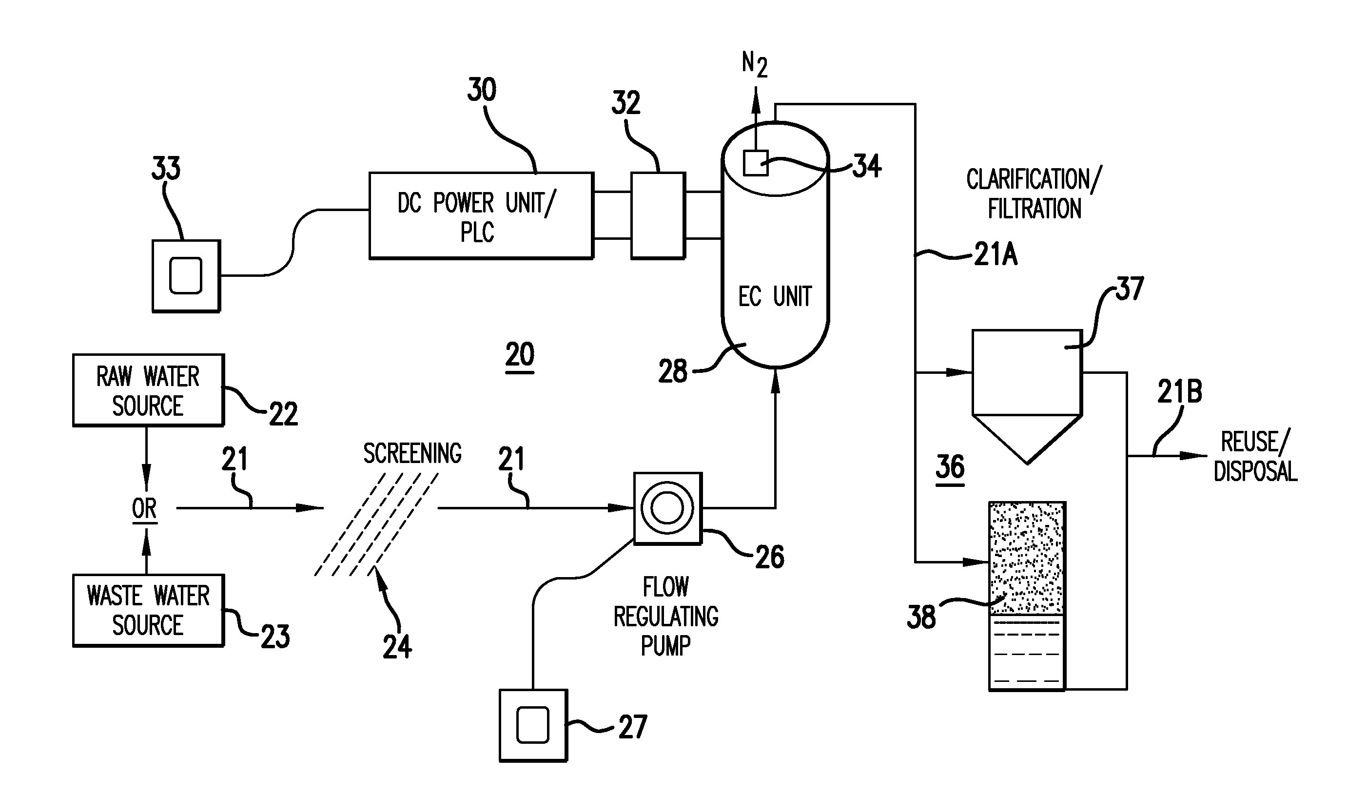
[0053]The systems described herein take advantage of selective electrode materials which offer advantages one over the other for the removal of a specific contaminant or a combination of contaminants that may be present in an aqueous stream, or to achieve a specific byproduct chemistry based on either the further intended treatment steps or the ultimate fate of the byproducts of which are to be disposed. Selective electrode materials may include, but are not limited to, iron, aluminum, titanium, carbon fiber, stainless steel or any other effective electrode material.
[0054]The systems described herein utilize specific electrode materials and configuration selection designed to achieve specific levels of treatment based on the specific contaminant or a combination of contaminants that are present at specific concentrations within the aqueous stream and the desired degree of treatment or removal. The variables which effect selective electrode material and configuration design include contaminants or the combination of contaminants to be removed, the concentrations of those contaminants, rates of flow, the pH of the aqueous streams and fluid conductivities. A resultant design is specifically developed to include selection of electrode material, electrode design configuration, electrode type, spacing between the electrodes, power to be applied and retention time in the electrochemical treatment unit selected. The resultant combination of variables results in both a specific electrical charge density or range and a specific ionic charge density or range.

Problems solved by technology

In the past chlorine was commonly used for the disinfection of both water and wastewater, but as a result of recognition by the US EPA that byproducts of chlorine may be potentially carcinogenic, new regulations have been passed limiting the widespread use of chlorine and requiring the reduction or elimination of disinfection byproducts.
Prior art attempts to improve systems and electrochemical treatment methods for wastewater treatment have not been satisfactory.
This typically results in rapid plugging or clogging of the treatment unit.
In the case of a single rod within a cylinder, often the spacing between the central rod and the perimeter wall is so great as to be ineffective in creating a sufficiently strong charge density to completely treat water or wastewater.
Due to the inefficiency of the plate designs, it was considered necessary to minimize plate spacings which quickly resulted in fouling of treatment units.
The center rod and tube designs experienced similar problems and attempted to use high voltage potentials to overcome ineffectiveness.
In every case, treatment technologies proved to be physically self-limiting and scaling factors (enlarging the units) became problematic.
Furthermore, these approaches were typically characterized by high energy consumption as attempts to reach intended treatment levels were explored.
This fact became a significant barrier to practical commercialization.
Previous attempts to develop effective electrochemical technologies for treatment of water and wastewater resulted in processes that were very expensive to operate and not effective.

Method used


Image

  • Electrochemical system and method for the treatment of water and wastewater
  • Electrochemical system and method for the treatment of water and wastewater
  • Electrochemical system and method for the treatment of water and wastewater

Examples


examples

[0145]a) When using the module 100 within the dielectric container structure 130 of FIGS. 13-16, a maximum power level of about 15 Kw per module is sufficient for various applications. The actual power level applied depends on the chemical make-up of the water being treated. Preferably, the 15 Kw power supply is capable of producing direct current at 500 amps and 30 volts, or any other combination of amperage or voltage within the 15 Kw envelope.

[0146]b) In a specific example, laundry water was treated at a DC power level of 400 amps and 9 volts with satisfactory results, however a higher amperage is thought to achieve better results. The satisfactory results were achieved at a pump speed of 16.5 U.S. gallons per minute (62.46 liters per minute) with a hydraulic retention time of about 2 minutes. Specifically, removal of contaminants was observed at 95 watts / gallon [9 volts×400 amps / 38 gallons (94.74 liters)].

[0147]c) Experiments on synthetic soapy samples using the module of FIGS. ...


PUM

PropertyMeasurementUnit
distanceaaaaaaaaaa
distanceaaaaaaaaaa
electrical gradientaaaaaaaaaa

Abstract

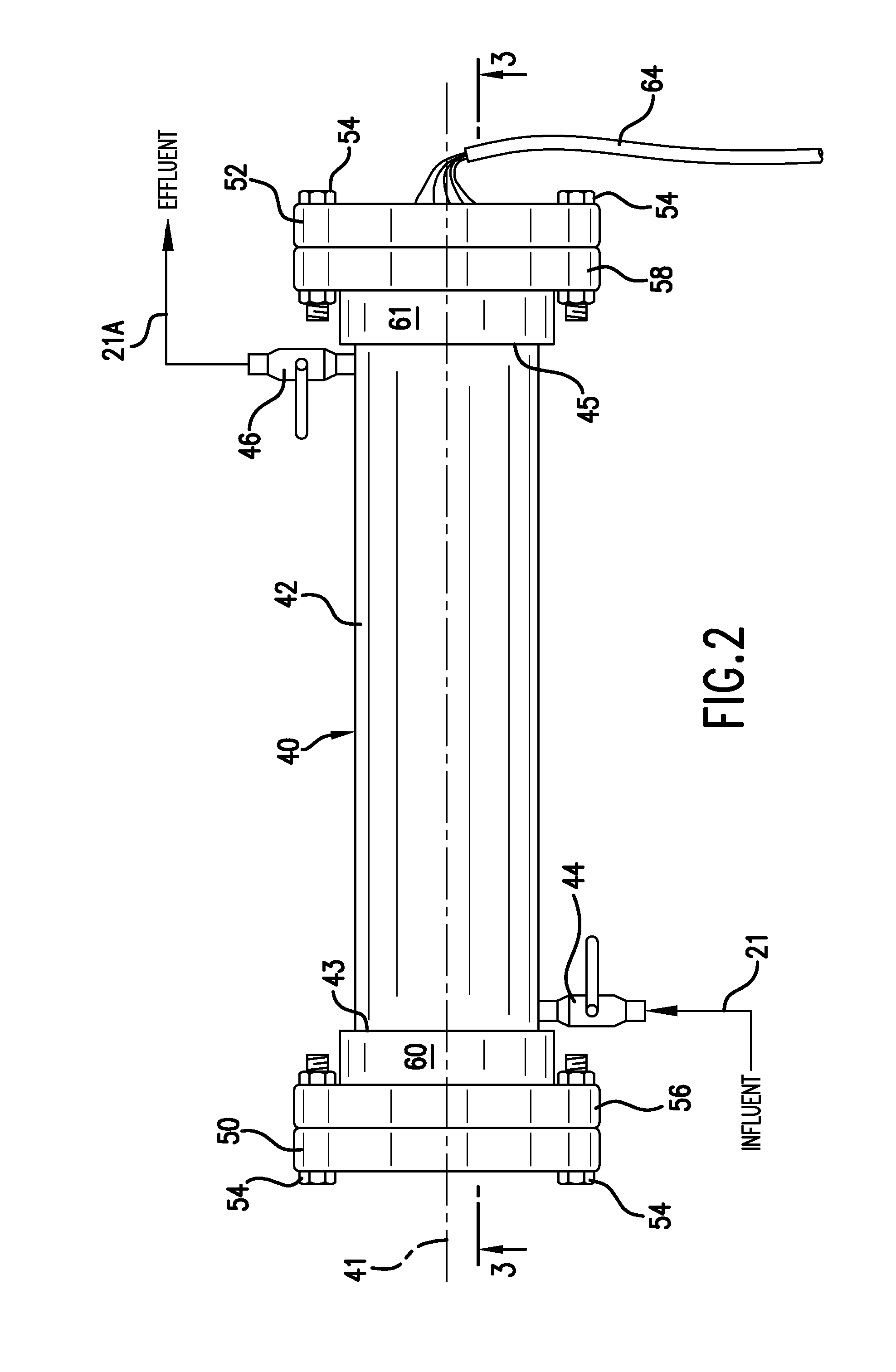
Contaminants are removed from untreated raw water or discharge water by applying direct current through an array of spaced, alternately charged electrodes positioned within and electrically isolated from a housing to eliminate or minimize clogging of the electrodes with precipitated contaminants. The housing is surrounded with container structure that cooperates with the housing to define an inlet chamber positioned between the source of untreated water and the housing containing the spaced array of electrodes. The container structure further includes an outlet chamber defined between the housing and the container structure for accumulating and draining water treated by the spaced electrode array.

Description

RELATED APPLICATIONS[0001]This application is a continuation-in-part of U.S. patent application Ser. No. 12 / 492,367, filed on Jun. 26, 2009, and claims the benefit of priority to Provisional Application No. 61 / 725,861, filed on Nov. 13, 2012, and Provisional Application No. 61 / 610,053, filed on Mar. 13, 2012. Each of above applications is incorporated herein by reference in its entirety.FIELD OF THE INVENTION[0002]This invention relates to water and wastewater treatment, and more particularly, but not limited to, treatment of surface water, groundwater, domestic sewage, industrial feed water, industrial process wastewater, hazardous and toxic wastes, liquid waste byproducts, the byproducts including, but not limited to, waste biosolids and membrane reject water, as well as but not limited to bilge water and waste water from ships.BACKGROUND OF THE INVENTION[0003]A variety of methods have been used to treat and remove contaminants from water and wastewater. The procedures and techniq...

Claims


Application Information

Patent Timeline
Patent Type & Authority Applications(United States)
IPC IPC(8): C02F1/461
CPCC02F1/46104C02F1/4602C02F2001/46119C02F2001/46152C02F1/46109C02F2201/46105C02F2201/4611C02F2201/4613C02F2201/4617C02F2201/008Y02W10/37
Inventor RIGBY, DAVID J.
Owner ELECTRO CHEM CORP
Why Eureka
Try Eureka