Heat storage system and installation method of latent heat storage material thereof

a technology of latent heat storage and heat storage system, which is applied in the direction of ventilation system, heating type, lighting and heating apparatus, etc., can solve the problems of large leakage of stored cold or warm heat and increase in weight, and achieve the effect of reducing the weight of the latent heat storage material

Inactive Publication Date: 2020-01-30
YAZAKI ENERGY SYST
View PDF0 Cites 1 Cited by
  • Summary
  • Abstract
  • Description
  • Claims
  • Application Information

AI Technical Summary

Benefits of technology

[0010]According to the present invention, both heating and cooling can be performed, and it is possible to achieve a reduction in a weight of the latent heat storage material to be used when storing heat over the season.

Problems solved by technology

For example, in a case of cold heat storage, it is conceivable to use ice having a melting point and a freezing point of 0° C. or use sodium acetate trihydrate having a melting point and a freezing point of 58° C. However, in the case of using these latent heat storage materials, since the melting point and the freezing point are low or high, leakage of stored cold or warm heat becomes large.
As a result, there is a possibility to lead to an increase in a weight.

Method used


Image

  • Heat storage system and installation method of latent heat storage material thereof
  • Heat storage system and installation method of latent heat storage material thereof
  • Heat storage system and installation method of latent heat storage material thereof

Examples


Embodiment Construction

[0017]Hereinafter, the present invention will be described in accordance with a preferred embodiment. The present invention is not limited to embodiments shown below and appropriate modifications can be made within the scope not departing from the gist of the present invention. Also, in an embodiment shown below, although there is a case where illustration or description of a part of a configuration is omitted, it is needless to say that, in details of the omitted technique, appropriately known or well-known techniques are applied within a range not inconsistent with the contents described below.

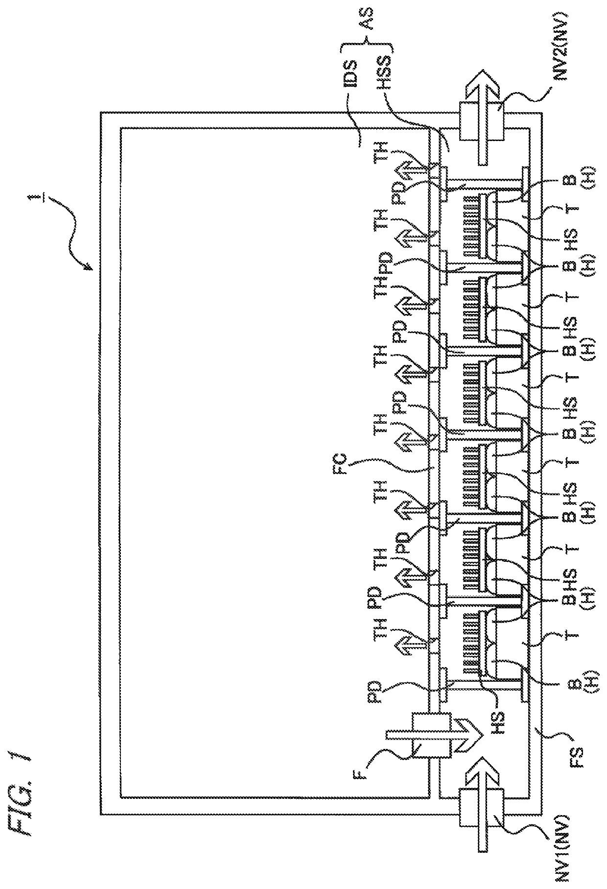
[0018]FIG. 1 is a configuration view illustrating a heat storage system according to an embodiment of the present invention. As shown in FIG. 1, a heat storage system 1 performs heating and cooling of an indoor space IDS, which is a space where people live or work, by using a latent heat storage material H, and is used for, for example, each floor of a building such as a high-rise building. ...


PUM


Abstract

There is provided a heat storage system including: an indoor space; a heat storage space which is adjacent to the indoor space and in which a latent heat storage material having a melting point or a freezing point in a range of 5° C. or higher and 30° C. or lower is installed; and a natural ventilator controlling introduction and blocking of outside air to the heat storage space, in which a heat resistance between the heat storage space and the outside air is set to be greater than a heat resistance between the heat storage space and the indoor space.

Description

CROSS REFERENCE TO RELATED APPLICATIONS[0001]This application is a continuation of PCT application No. PCT / JP2018 / 012612, which was filed on Mar. 27, 2018 based on Japanese patent application 2017-076791 filed on Apr. 7, 2017, whose contents are incorporated herein by reference. Also, all the references cited herein are incorporated as a whole.BACKGROUND OF THE INVENTION1. Technical Field[0002]The present invention relates to a heat storage system and an installation method of a latent heat storage material thereof.2. Background Art[0003]In the related art, by focusing on a daily temperature range of an outside temperature, a system that stores cold heat or warm heat, which is necessary for daily use, under a floor or the like for approximately half a day and uses the heat for air conditioning, in order to use an air conditioning effect using nighttime cold heat or midnight power before noon or use power deviated from peak power demand is proposed (see Patent Literatures JP-A-2000-2...

Claims


Application Information

Patent Timeline
Patent Type & Authority Applications(United States)
IPC IPC(8): F28D20/02
CPCF28D20/021F28D20/02F24F5/0021F24F7/10F24F13/0227F28F27/00F24D19/1084F24D5/10F28F2265/16F28D2020/0021F28D20/023F28F2265/14F28F3/06E04F15/02405E04F15/02494Y02E60/14
Inventor NAKAMURA, TAKUJUGUNJI, KAI
Owner YAZAKI ENERGY SYST
Why Eureka
Try Eureka