Lid for Airtight Containers

a technology for airtight containers and lids, applied in the direction of caps, applications, liquid handling, etc., can solve the problems of increasing creep, relatively large load on the film hinge, and different dimensions of the manufactured container bodies b>10/b>, etc., and achieve the effect of improving the durability of the lid

Active Publication Date: 2009-09-03
SUK JONG CHEUL
View PDF23 Cites 47 Cited by
  • Summary
  • Abstract
  • Description
  • Claims
  • Application Information

AI Technical Summary

Benefits of technology

[0014]Accordingly, the present invention has been made keeping in mind the above problems occurring in the prior art, and an object of the present invention is to provide a lid for an airtight container which is configured such that the impact occurring when the lid is locked to the container body to seal the container body is minimized, thus improving the durability of the lid.
[0015]Another object of the present invention is to provide a lid for airtight container which is configured such that the smooth flow of raw material when forming the lid is ensured, thus preventing production defects.

Problems solved by technology

First, synthetic resin or glass is typically used as raw material for the conventional container body 10. In the case of such material, due to a thermal change in the state between molecules, a contraction phenomenon, by which the dimensions of the container body 10 are reduced and the shape of the container body 10 thus varies, is induced. Hence, the dimensions of the manufactured container bodies 10 may become different from each other.
However, in the case where the length l is relatively long, when the locking protrusion 22 is locked to the locking groove 11, a relatively large load is applied to the film hinge 23, thus increasing creep.
As a result, a crack may occur in the film hinge 23, with the result that the film hinge 23 tears.
As a result, the film hinge 23 may be damaged, particularly, easily tear.
Hence, there is a problem in that a defective forming phenomenon, such as an unforming or albinic phenomenon, may occur in the event that material is insufficiently charged into the portion of the mold corresponding to the film hinge 23 when forming the lid 20.

Method used


Image

  • Lid for Airtight Containers
  • Lid for Airtight Containers
  • Lid for Airtight Containers

Examples


Embodiment Construction

[0023]Hereinafter, a preferred embodiment of the present invention will be described in detail with reference to the attached drawings.

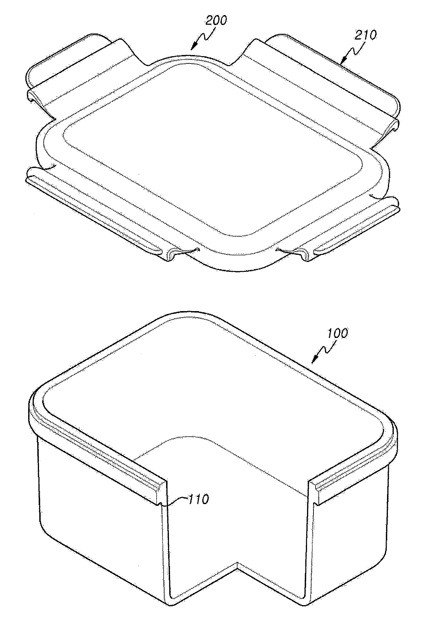
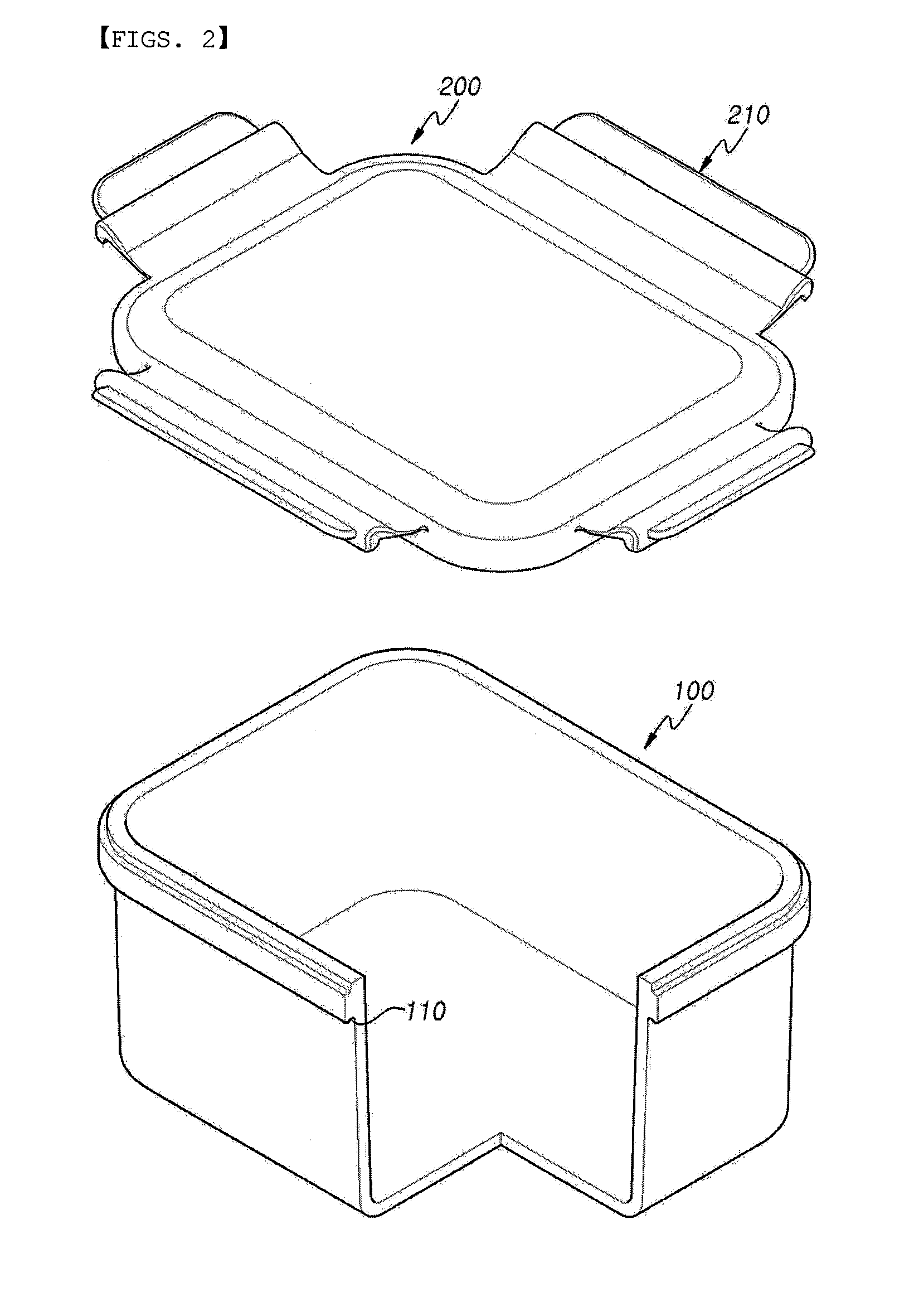
[0024]In the present invention, as shown in FIG. 2, an airtight container includes a container body 100, which is open on the upper end thereof to contain food therein, and a lid 200, which seals the open upper end of the container body 100.

[0025]In FIG. 2, although the container body 100 is illustrated as having a rectangular shape and the lid 200 is illustrated as having a rectangular plate shape, those skilled in the art will appreciate that the container body 100 can have other various shapes, for example, a cylindrical shape or a polyhedral shape, and that the lid 200 can be formed to have a shape corresponding to the container body 100.

[0026]In the present invention, a locking depression 110 is formed in the circumferential outer edge of the open upper end of the container body 100, so that locking protrusions 212 of the lid 200, which will be ...


PUM

PropertyMeasurementUnit
lengthaaaaaaaaaa
thicknessaaaaaaaaaa
thickaaaaaaaaaa

Abstract

Disclosed herein is a lid for airtight containers. The lid according to the present invention includes a plurality of locking flap handles, which are coupled to a lid body so as to be rotatable, and each of which has a locking protrusion to be locked to a locking depression formed in the outer edge of the upper end of a container body. The locking flap handles are connected to the lid body by respective film hinges. The film hinge includes an elastic hinge part, which is continuous with the upper surface of the lid without having a stepped portion and is curved outwards at a predetermined curvature, and a connection part, which connects the elastic hinge part to the locking flap handle. The connection part extends a predetermined length to disperse an impact generated when the locking flap handle is locked to the container body. Thus, when the locking flap handle is locked to the container body, the elastic hinge part is folded around an inner corner, which forms a boundary between the elastic hinge part and the lid body, and is elastically brought into contact with the outer surface of the lid body.

Description

BACKGROUND OF THE INVENTION[0001]1. Field of the Invention[0002]The present invention relates generally to lids for airtight containers and, more particularly, to a lid for an airtight container which is configured such that the impact generated when locking the lid to the container body is minimized, thus improving the durability of the lid, and such that the smooth flow of raw material is ensured when forming the lid, thus preventing production defects.[0003]2. Description of the Related Art[0004]As well known to those skilled in the art, airtight containers contain and store food therein. Such an airtight container includes a container body, which is open on the upper end thereof to contain food therein, and a lid, which seals the open upper end of the container body.[0005]FIGS. 1A and 1B are enlarged sectional views showing critical parts of a container body 10 and a lid 20 to illustrate the coupling therebetween, according to a representative example of the conventional techniq...

Claims


Application Information

Patent Timeline
Patent Type & Authority Applications(United States)
IPC IPC(8): B65D41/16
CPCB65D43/0212B65D85/72B65D2543/00518B65D2543/00796B65D2543/00555B65D2543/0074B65D2543/00537B65D43/08B65D45/16
Inventor SUK, JONG CHEUL
Owner SUK JONG CHEUL
Why Eureka
Try Eureka