Liquid transport apparatus and method for producing liquid transport apparatus

a technology of liquid transport apparatus and liquid transport actuator, which is applied in the direction of printing, etc., can solve the problems of deteriorating driving stability of piezoelectric actuator, complex shape of common electrode, and local instability of electric potential of common electrode, so as to suppress the occurrence of piezoelectric strain

Active Publication Date: 2009-09-03
BROTHER KOGYO KK
View PDF1 Cites 26 Cited by
  • Summary
  • Abstract
  • Description
  • Claims
  • Application Information

AI Technical Summary

Benefits of technology

[0057]According to the present invention, the insulating layer is formed to overlap with the portions, of the wirings, passing the inter-electrode areas. Therefore, it is unnecessary to partially cut out the common electrode in the areas opposed to the wirings in order that no piezoelectric strain is generated in the piezoelectric layer in the areas in which the wirings are arranged. Therefore, it is possible to suppress the occurrence of the piezoelectric strain in the areas between the individual electrodes through which the wirings are allowed to pass, while stabilizing the electric potential of the com...

Problems solved by technology

In other words, if the areas of the common electrode, which are opposed to the wiring sections, are partially cut as in the piezoelectric actuator described in Japanese Patent Application Laid-open No. 2005-349568, the sha...

Method used


Image

  • Liquid transport apparatus and method for producing liquid transport apparatus
  • Liquid transport apparatus and method for producing liquid transport apparatus
  • Liquid transport apparatus and method for producing liquid transport apparatus

Examples


first modified embodiment

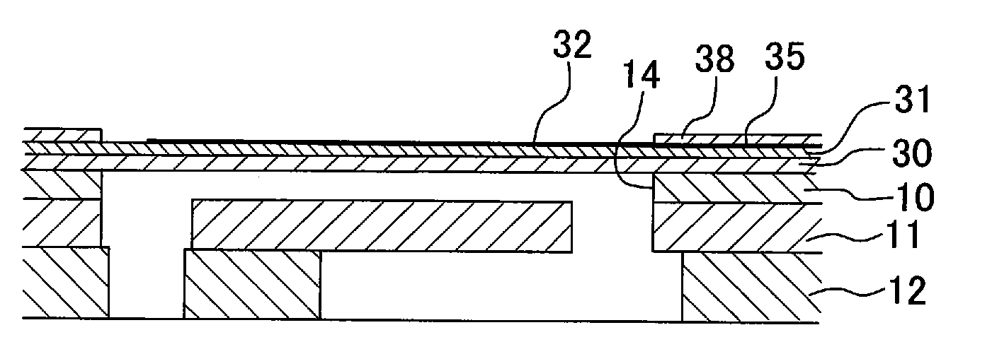
[0109]In a first modified embodiment, as shown in FIG. 9, the area of the vibration plate 30, in which the piezoelectric layer 33 is arranged, may be fixed to the upper surface of the channel unit 4 to cover the plurality of pressure chambers 14 therewith, while the area, in which the piezoelectric layer 33 is not arranged, may be allowed to extend to the outside of the channel unit 4, and the driver IC 37 (driving circuit), which is connected to the plurality of wiring sections 35 covered with the second insulating layer 38, may be further carried on the extended portion. In this way, when the part of the vibration plate 30 is used as the wiring board provided with the plurality of wiring sections 35 and the driver IC 37 connected thereto, it is preferable that the portion, which is used as the wiring board, is maximally thinned so that the portion can be easily curved and laid out. Accordingly, in the embodiment shown in FIG. 9, the piezoelectric layer 33 is not formed on the port...

second modified embodiment

[0110]When the piezoelectric strain is generated in the piezoelectric layer 33 interposed between a certain wiring section 35 and the common electrode 34, the piezoelectric strain, which is generated at the portion of the piezoelectric layer 33 disposed closely to the individual electrode 32, exerts the worst influence on the another pressure chambers 14. That is, the piezoelectric strain generated at the portion allowed to pass between the individual electrodes 32 exerts the worst influence on the another pressure chambers 14. Accordingly, in a second modified embodiment, as shown in FIG. 10, the second insulating layer 38 may be formed in only the area (area B shown in FIG. 10) in which the wiring section 35 is allowed to pass between the another individual electrodes 32. Even in this case, the height position of the upper surface of the piezoelectric layer 33, which is provided in the active area arranged to be overlapped with the individual electrodes 32, is lower than those of ...


PUM


Abstract

A piezoelectric actuator includes a vibration plate, a plurality of individual electrodes, wiring sections each extending from corresponding one of the individual electrodes and passing between the other individual electrodes other than the corresponding individual electrode, a piezoelectric layer arranged on the vibration plate to cover the individual electrodes, and a common electrode arranged on a surface of the piezoelectric layer disposed on a side opposite to the piezoelectric layer. At least portions of the plurality of wiring sections, each of which is allowed to pass between the another individual electrodes, are covered with a second insulating layer. Accordingly, it is possible to suppress the occurrence of the strain of the piezoelectric layer in the area between the individual electrodes through which the wiring section is allowed to pass, without providing any complicated shape of the common electrode in which the common electrode is partially cut out.

Description

CROSS REFERENCE TO RELATED APPLICATION[0001]The present application claims priority from Japanese Patent Application No. 2008-050291, filed on Feb. 29, 2008 the disclosures of which are incorporated herein by reference in its entirety.BACKGROUND OF THE INVENTION[0002]1. Field of the Invention[0003]The present invention relates to a liquid transport apparatus for transporting a liquid, and a method for producing the liquid transport apparatus.[0004]2. Description of the Related Art[0005]An ink-jet head, which jets an ink liquid from nozzles, has been hitherto known as a liquid transport apparatus for transporting the liquid, the ink-jet head including a channel unit which is provided with a plurality of pressure chambers communicated with the nozzles respectively, and a piezoelectric type actuator which selectively applies the pressure to the plurality of pressure chambers.[0006]An ink-jet head described in Japanese Patent Application Laid-open No. 2005-349568 includes a piezoelectri...

Claims


Application Information

Patent Timeline
IPC IPC(8): B41J2/045
CPCB41J2/14233B41J2002/14491B41J2002/14266
Inventor SUGAHARA, HIROTO
Owner BROTHER KOGYO KK
Why Eureka
Try Eureka