Electrical connector
a technology of electric connectors and connectors, applied in the direction of electrical equipment, coupling contact components, printed circuits, etc., can solve the problems of affecting the operation of the connector, the insertion protrusion may not reach the position right under the regulating step portion, and the terminal may come off, so as to achieve sufficient strength and expand the dimensions of the regulating wall portion
- Summary
- Abstract
- Description
- Claims
- Application Information
AI Technical Summary
Benefits of technology
Problems solved by technology
Method used
Image
Examples
first embodiment
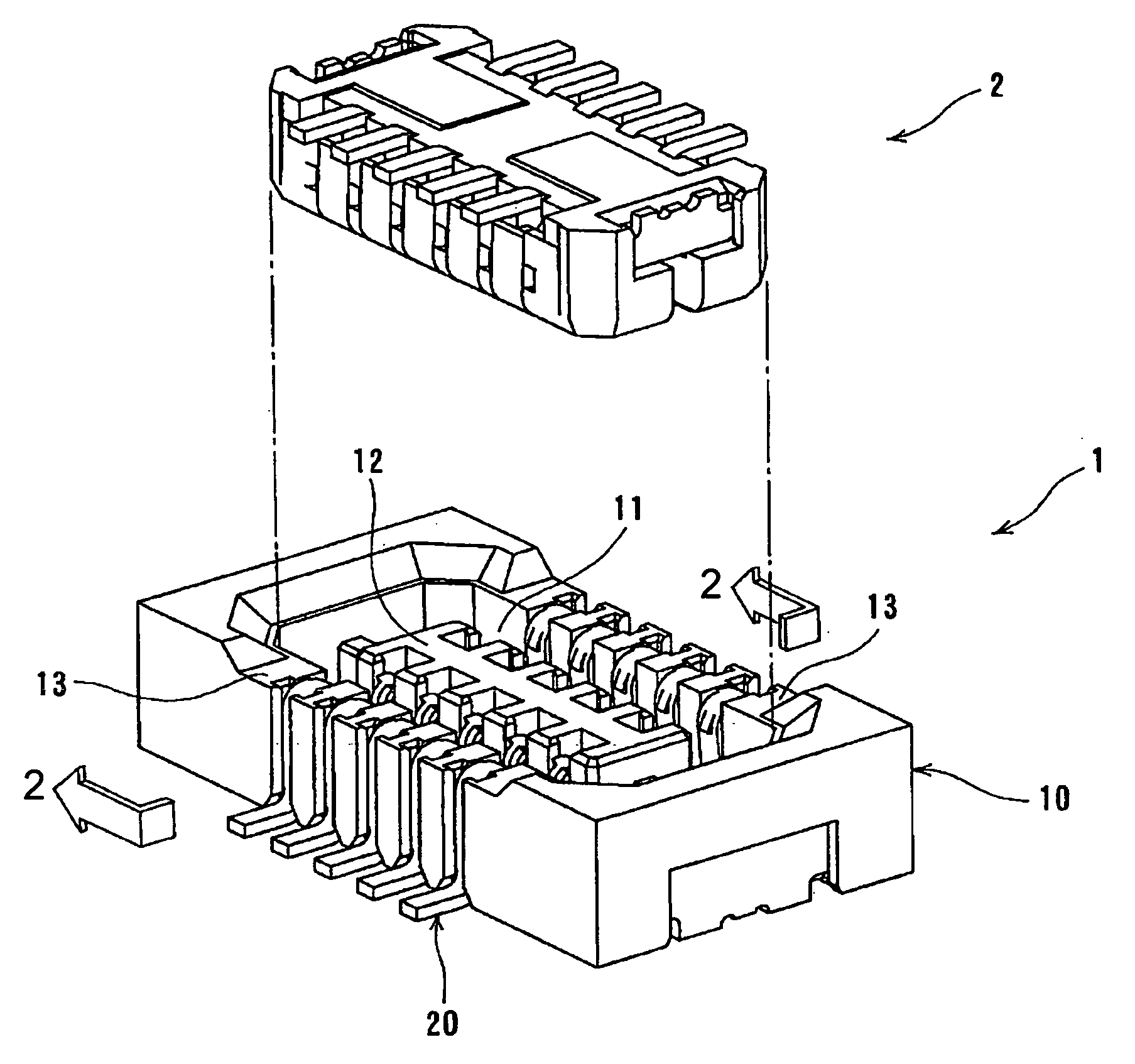
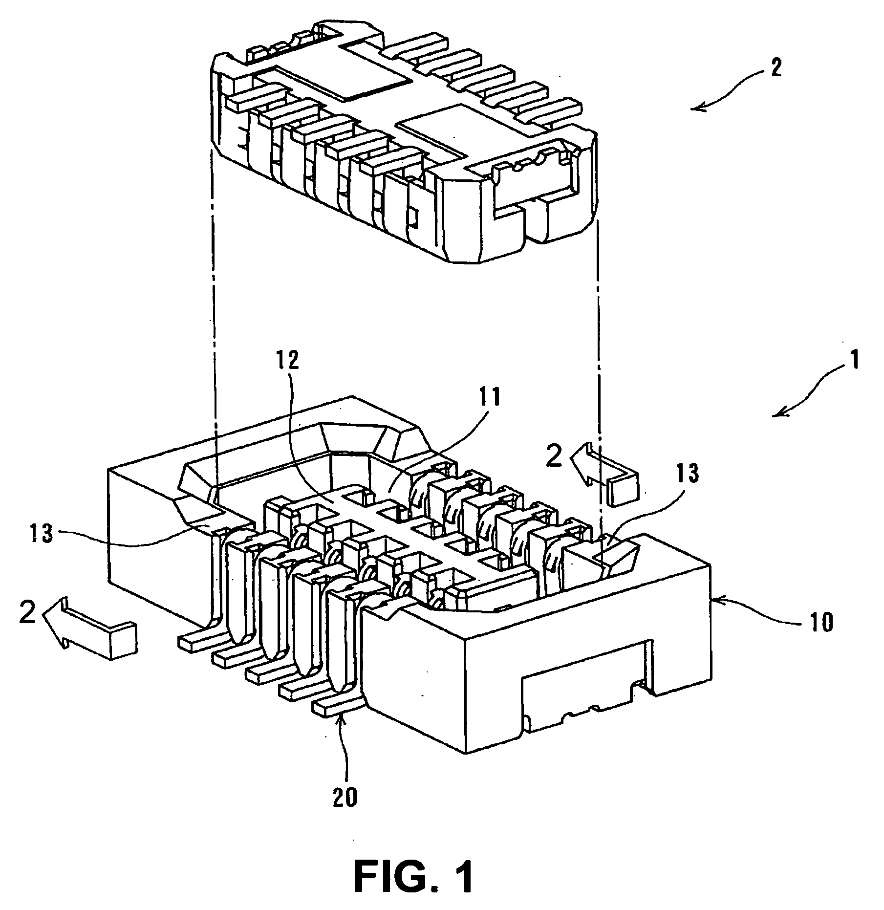
[0036]FIG. 1 is a perspective view showing an electrical connector 1 (connector) and a mating connector 2 to be connected thereto according to a first embodiment of the present invention.
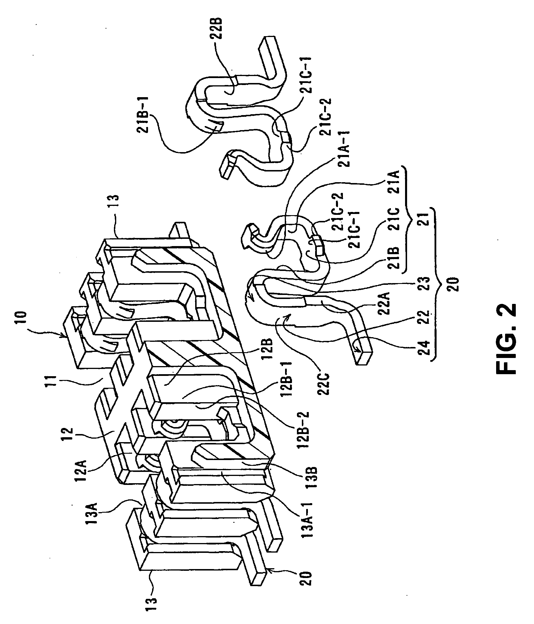
[0037]The connector 1 includes a housing 10 with an approximate rectangular solid shape and made of a synthetic resin; and a plurality of terminals 20 aligned and held in the housing 10. The housing 10 includes a receptacle recess portion 11 inside a circumference wall thereof for connecting the mating connector 2; and a central wall 12 having an approximate rectangular solid shape and located insularly at a central portion of the receptacle recess portion 11. Accordingly, the receptacle recess portion 11 is formed by an inner surface of the circumference wall, an outer circumference surface of the central wall 12, and an inner surface of a bottom wall of the housing 10. Two wall portions of the circumference wall of the housing 10 facing each other and extending in a longitudinal direction are form...
second embodiment
[0065]In the second embodiment, a basic structure of the connector 1 is the same as the connector 1 in the first embodiment. Accordingly, differences from the first embodiment will be mainly explained. The same reference numerals as the first embodiment denote the same components, respectively, and explanations thereof are omitted.
[0066]FIG. 5 is a sectional view showing a partial view of the connector 1 in the connecting direction of the connectors taken along a plane perpendicular to the connecting direction of the connectors according to a second embodiment of the present invention. In FIG. 5, one pair of the terminals 20 facing one another is shown as being removed from the housing 10.
[0067]In the embodiment, the engaging portion 21A-2 is formed on the contact arm portion 21A of the terminal 20 of the connector 1 instead of the transition portion 21C. As shown in FIG. 5, the engaging portion 21A-2 of the contact arm portion 21A is formed at a lower area of the contact portion 21...
third embodiment
[0083]In the third embodiment, a basic structure of the connector 1 is similar to that of the connector 1 in the first embodiment and the second embodiment. Accordingly, differences from the first embodiment or the second embodiment will be mainly explained. The same reference numerals as the first and second embodiments denote the same components, respectively, and explanations thereof are omitted.
[0084]FIG. 8 is a perspective view of the terminal 20 of the connector 1 according to the third embodiment. As shown in FIG. 8, the terminal 20 in the embodiment has the same basic structure as the terminal in the first and second embodiments. In the third embodiment, the terminal has two engaging portions at the side end edge thereof. More specifically, the terminal 20 has an engaging portion 21C-1 at the side end edge of the transition portion 21C and the engaging portion 21A-2 at the side end edge of the contact arm portion 21A, that is, the terminal 20 has a shape having both of the e...
PUM
 Abstract
Description
Claims
Application Information
 - R&D
- Intellectual Property
- Life Sciences
- Materials
- Tech Scout
- Unparalleled Data Quality
- Higher Quality Content
- 60% Fewer Hallucinations
Browse by: Latest US Patents, China's latest patents, Technical Efficacy Thesaurus, Application Domain, Technology Topic, Popular Technical Reports.
© 2025 PatSnap. All rights reserved.Legal|Privacy policy|Modern Slavery Act Transparency Statement|Sitemap|About US| Contact US: help@patsnap.com


