
Method and Apparatus for the Identification and Position Measurement of Chips on a Gaming Surface

Active Publication Date: 2009-09-03
TECHNOLOGY CAPITAL LLC
View PDF12 Cites 26 Cited by
  • Summary
  • Abstract
  • Description
  • Claims
  • Application Information

AI Technical Summary

Benefits of technology

[0009]The present invention addresses the needs described above by accurately determining the position of a plurality of gaming chips disposed in closely spaced betting zones on a blackjack gaming table.

Problems solved by technology

Such capability has, up to now, been impossible to achieve, within reasonable budgets and with existing technologies, but it nevertheless still remains extremely high in the list of the casino managers' priorities.
However, although promising, this technology presents a major drawback: it is not particularly precise in terms of spatial resolution and, as a result, its potential is limited to gaming surfaces with single betting areas, such as poker tables, or to tables with very spaced out betting areas.
Because of both its operating principle and the frequencies at which it operates, this technology is subject to effects that disturb the local field.
Consequently, it is easy to see why, when dealing with gaming surfaces with multiple, closely spaced, betting areas, such as the ones used in blackjack or baccarat, or, even worse, with gaming surfaces in which chips may legitimately ride on the separation lines between betting areas, such as roulette tables, existing RFID based technology is inadequate.
However, even though this technology is clearly superior to other existing RFID technology, it may not be, by itself, used to achieve accurate enough coverage over closely spaced betting zones.
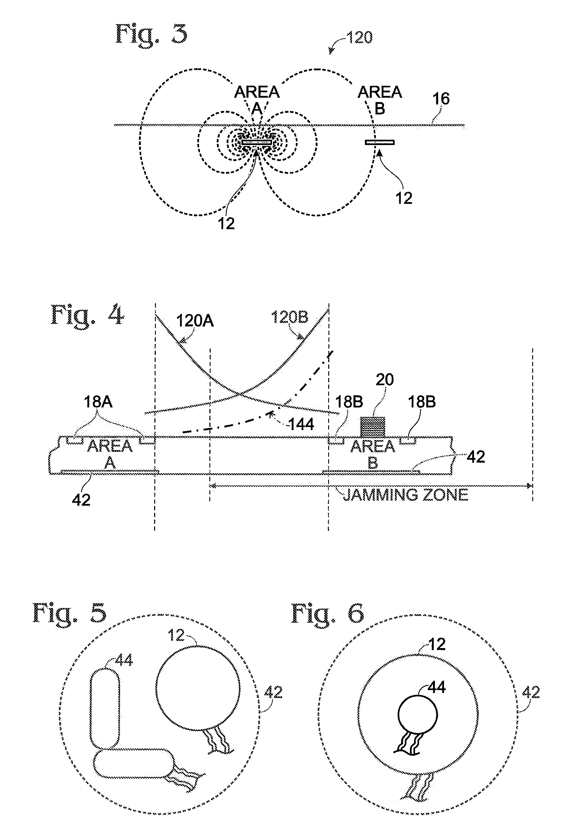
This implies that when the diagonal of the betting area is smaller than the height of the top of a 25 chip stack, and that an adjacent betting area is situated quite close to the observed betting area, it is generally impossible to achieve the required “drop off” characteristics.

Method used


Image

  • Method and Apparatus for the Identification and Position Measurement of Chips on a Gaming Surface
  • Method and Apparatus for the Identification and Position Measurement of Chips on a Gaming Surface
  • Method and Apparatus for the Identification and Position Measurement of Chips on a Gaming Surface

Examples


Embodiment Construction

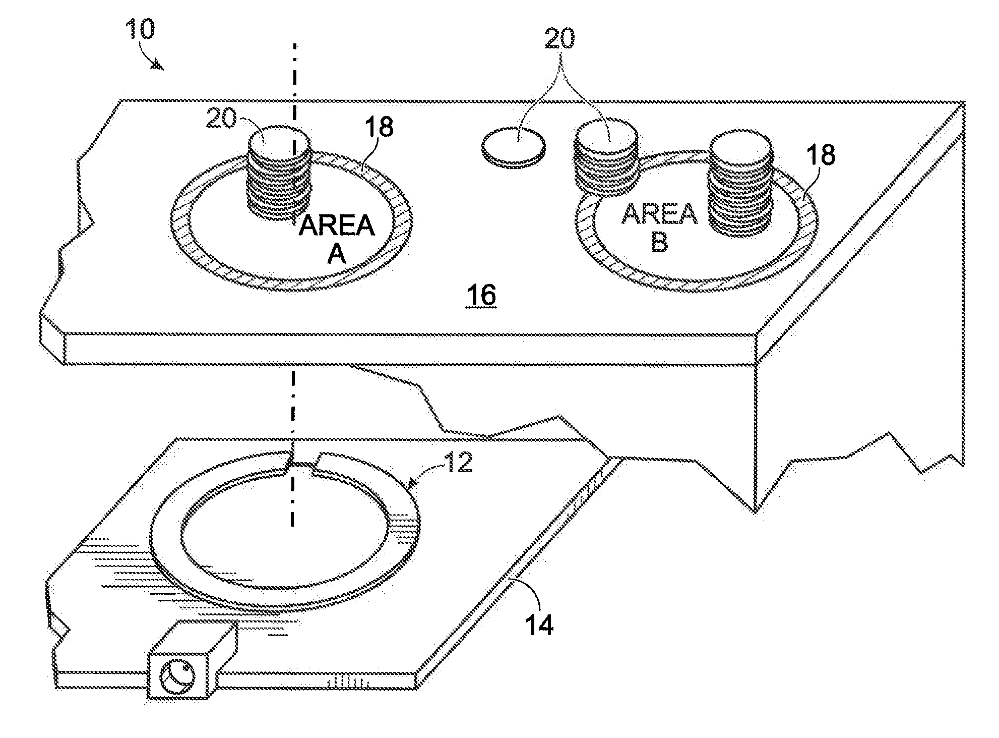
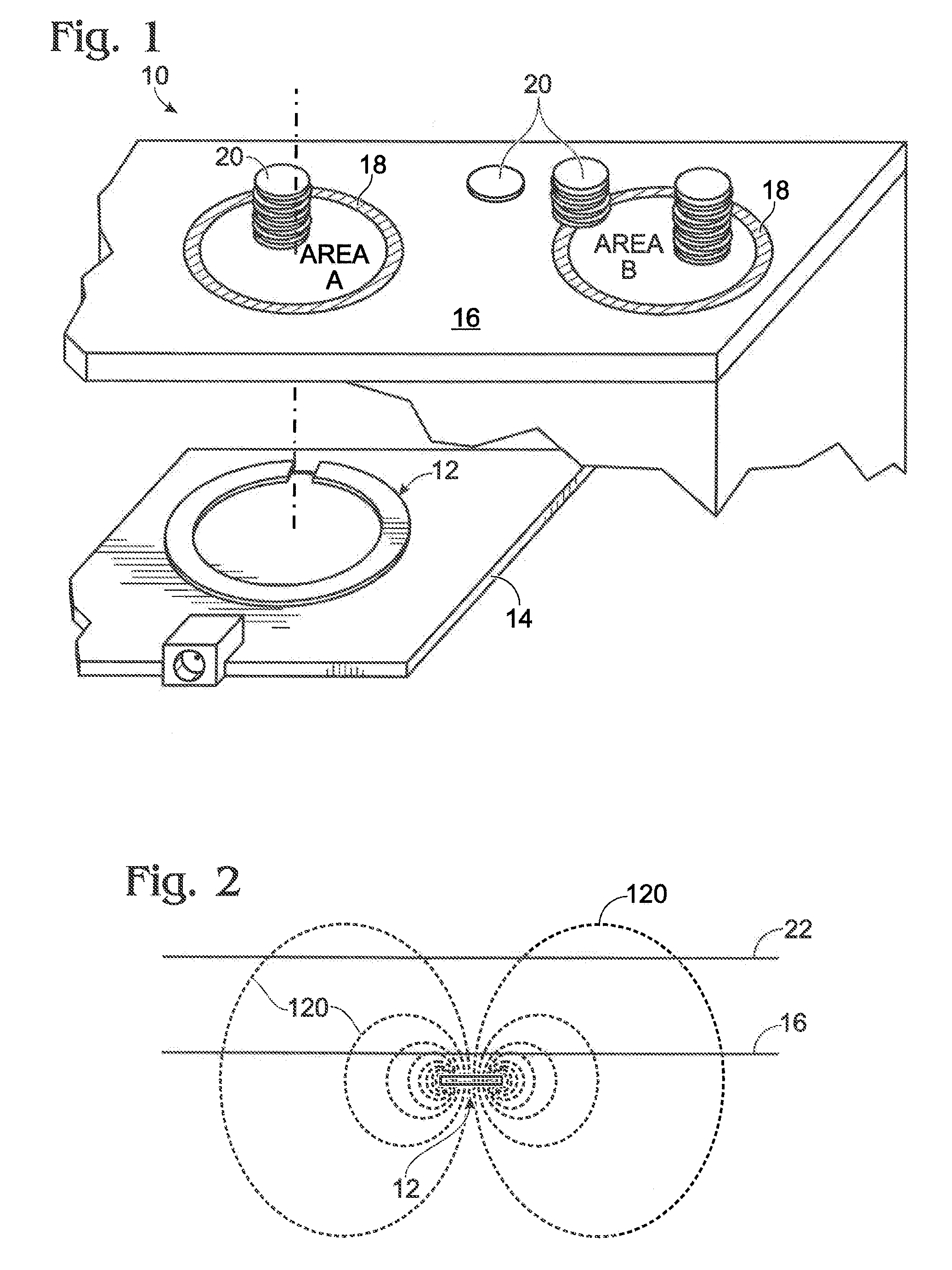
[0028]Reference will now be made in detail to the present exemplary embodiments of the invention, examples of which are illustrated in the accompanying drawings. Wherever possible, the same reference numbers will be used throughout the drawings to refer to the same or like parts. An exemplary embodiment of the gaming surface of the present invention is shown in FIG. 1, and is designated generally throughout by reference numeral 10.

[0029]Generally stated, a method and apparatus according to illustrative embodiments of the present invention provide improved spatial resolution of magnetic coupling RFID technology used to identify the position of chips on precisely defined betting areas on a gaming surface, such as, for example, a gaming table. The method and apparatus provide gaming surface modifications which allow the use of magnetically coupled RFID gaming chips where tight spacing is needed and no “cross reading” of chips in other betting zones is desired. The use of “active field ...


PUM


Abstract

The present invention is directed to a method for determining a position of each of a plurality of gaming chips on a gaming surface. Each of the plurality of gaming chips includes an inductively coupled RFID tag disposed therein. The gaming surface includes a first area and at least one second area disposed adjacent to the first area. The method includes transmitting a near-field inductively coupled interrogation signal to the plurality of gaming chips. A near-field inductively coupled response signal is received from at least a portion of the plurality of gaming chips. A position resolution action is performed in conjunction with either the step of transmitting or the step of receiving. Each of the plurality of gaming chips are associated with either the first area or the at least one second area in accordance with the step of performing a position resolution action.

Description

CROSS-REFERENCE TO RELATED APPLICATIONS[0001]This is a U.S. National Stage submission under 35 U.S.C. §371 of International Patent Application Serial No. PCT / CA2006 / 001716 filed on 20 Oct. 2006, International Patent Application Serial No. PCT / CA2006 / 001716 claims priority under 35 U.S.C. § 119 (e) to U.S. Provisional Patent Application Ser. No. 60 / 728,761 filed on 21 Oct. 2005, the contents of which are relied upon and incorporated herein by reference in their entirety.1. FIELD OF THE INVENTION[0002]The present invention relates to a method and apparatus for the identification and position measurement of chips on a gaming surface. More specifically, the present invention relates to a method and system for improving the spatial resolution of magnetic coupling RFID technology to identify and measure the position of chips on precisely defined betting areas on a gaming table.2. TECHNICAL BACKGROUND[0003]Casino managers have always been interested in being able to record in real time all...

Claims


Application Information

Patent Timeline
IPC IPC(8): A63F9/24
CPCA44C21/00
Inventor RICHARD, CHRISTIANMILLER, RON N.
Owner TECHNOLOGY CAPITAL LLC
Learn More