Telescoping support bar

a technology of telescoping support and support rod, which is applied in the direction of curtain suspension devices, baths, curtains, etc., can solve the problems of mass production of bath and shower assist means

Inactive Publication Date: 2009-09-10
GRANT WILLIE T +1
View PDF16 Cites 19 Cited by
  • Summary
  • Abstract
  • Description
  • Claims
  • Application Information

AI Technical Summary

Benefits of technology

[0003]The present invention overcomes these shortcomings and other limitations by providing telescoping means that incorporate multiple tubes that are radially compatible and telescope from a minimum length to a maximum length bar. This variable feature in the length of the bar permits the same support bar to be used for a range of sizes of shower enclosures, generally eliminating the need to custom-cut a different length wall-to-wall bar for each facility.
[0005]One of the principal objectives of the present invention is to provide telescoping support means that can be easily assembled, installed, and removed without the use of mechanical fasteners.
[0006]Another objective is to provide telescoping support means with longitudinal adjustability to accommodate a range of shower and other facility dimensions thereby eliminating the need to custom-build each support bar.
[0007]Another objective is to provide a support bar having easy release means thereby giving it location mobility within an enclosure.

Problems solved by technology

This requirement prevents mass production of the bath and shower assist means.

Method used


Image

  • Telescoping support bar
  • Telescoping support bar

Examples


Embodiment Construction

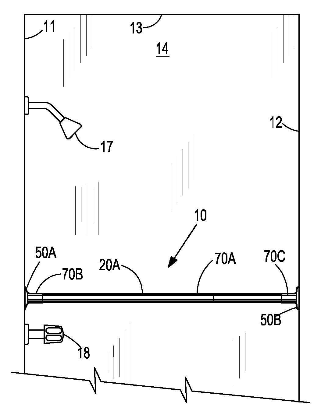
[0011]Referring to the drawing more specifically, FIG. 1 references telescoping support bar 10 (hereafter called support bar) constructed according to the present invention for installation in shower enclosures or tub / shower facilities having walls 11, 12, and 14 and ceiling 13. Shown also in FIG. 1 are shower head 17 and faucet 18 attaching to said wall 11.

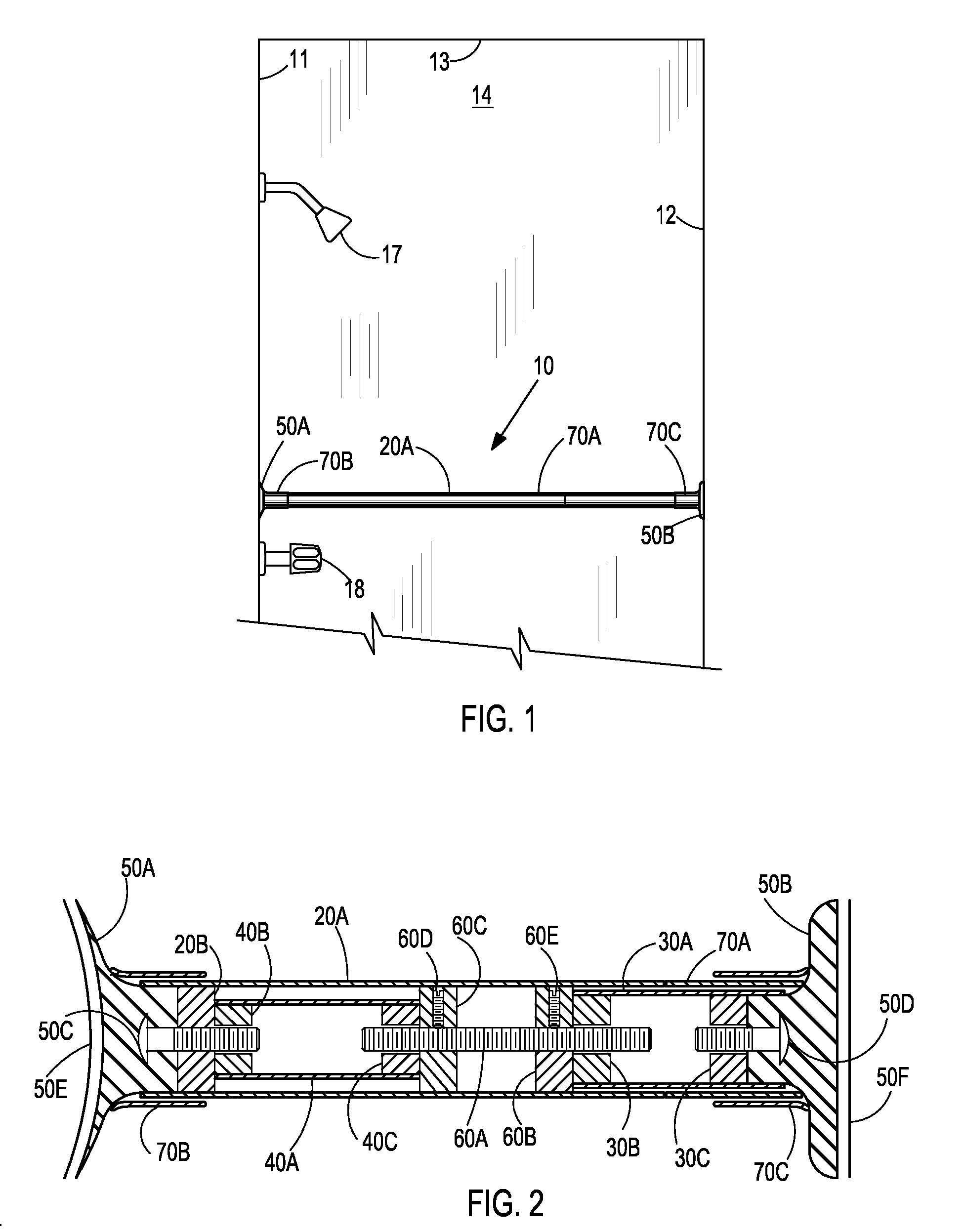
[0012]Referring to FIG. 2, said support bar comprises retaining means 50, said means having retainers 50A and 50B with embedded studs 50C and 50D respectively. Support bar 10 incorporates rotatable means 20, said rotatable means comprising larger diameter tube 20A with first bearing 20B. Tube 20A of rotatable means 20 telescopes cooperates with a slightly smaller diameter tube 30A, of telescoping means 30; said tube 30A translates longitudinally in and out of larger diameter tube 20A of rotatable means 20. Said tubes 20A and 30A connect to retainers 50A and 50B respectively through first bearing means 20B and fourth bearing means...


PUM


Abstract

A telescoping support bar installed in a shower enclosure and similar facilities requires no mechanical wall fasteners. The support bar includes telescoping tubes with end retainers gripping walls of the enclosures. Length of the support bar is governed by fixed length spacer means and internal extensible means. Extensible means, having bearings movable along a rod, provides the lengthening and shortening of the support bar as the distance between the bearings is increased or decreased. This change in distance likewise changes the overall length of the support bar. With the retainers snug against the walls, one of the tubes, being rotatable, is turned in circular motion. This rotation is converted into an axial force along the bar causing the retainers to forcefully grip the walls, providing a rigid and strong bar installation.

Description

BACKGROUND OF THE INVENTION[0001]Patent application Ser. No. 11 / 684,611 sets forth a wall-to-wall grip bar for use in a shower or bath / shower enclosure. The horizontal grip bar is the core of the invention. One of the shortcomings of the invention in the patent application is the necessity that each bar be custom made according to the dimension of the particular shower enclosure in which it will be installed. This requirement prevents mass production of the bath and shower assist means.[0002]Also in patent application Ser. No. 11 / 684,611 sealing means are defined to be attached to the covering means that encapsulate the compression and tension elements that engage the wall faces of the shower enclosures. A stronger support system is provided if the sealing means also serves as bonding means between the tiles of the shower walls and the contact surfaces of the compression and tension means.SUMMARY OF THE INVENTION[0003]The present invention overcomes these shortcomings and other limi...

Claims


Application Information

Patent Timeline
Patent Type & Authority Applications(United States)
IPC IPC(8): A47H1/08
CPCA47K3/38
Inventor GRANT, WILLIE T.GRANT, CAROLYN R.
Owner GRANT WILLIE T
Why Eureka
Try Eureka