Application of eddy current braking system for use in a gearbox/generator mechanical disconnect

a technology of eddy current braking and gearbox, which is applied in the direction of motor/generator/converter stopper, electric generator control, dynamo-electric converter control, etc., can solve the problem of difficulty in designing a shear section that can protect the gear box regardless

Inactive Publication Date: 2009-09-10
HONEYWELL INT INC
View PDF10 Cites 24 Cited by
  • Summary
  • Abstract
  • Description
  • Claims
  • Application Information

AI Technical Summary

Problems solved by technology

However, with the evolution of variable frequency generators (VFG), where failure can occur over a range of speeds, it is rather difficult to design a shear section that can protect the gear box regardless of the multiple possible speeds of the generator.

Method used


Image

  • Application of eddy current braking system for use in a gearbox/generator mechanical disconnect
  • Application of eddy current braking system for use in a gearbox/generator mechanical disconnect
  • Application of eddy current braking system for use in a gearbox/generator mechanical disconnect

Examples


Embodiment Construction

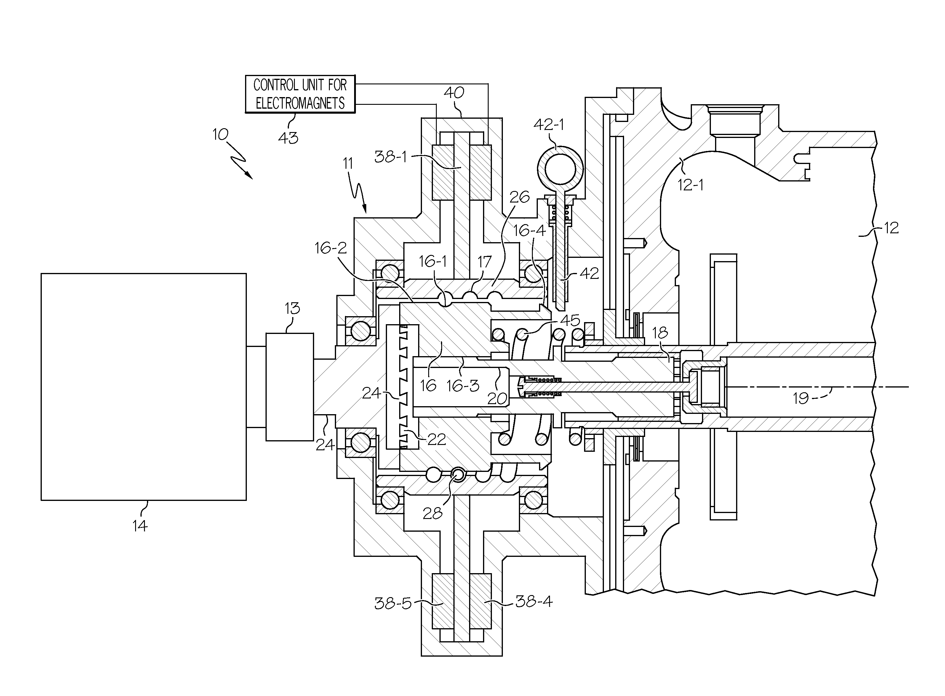
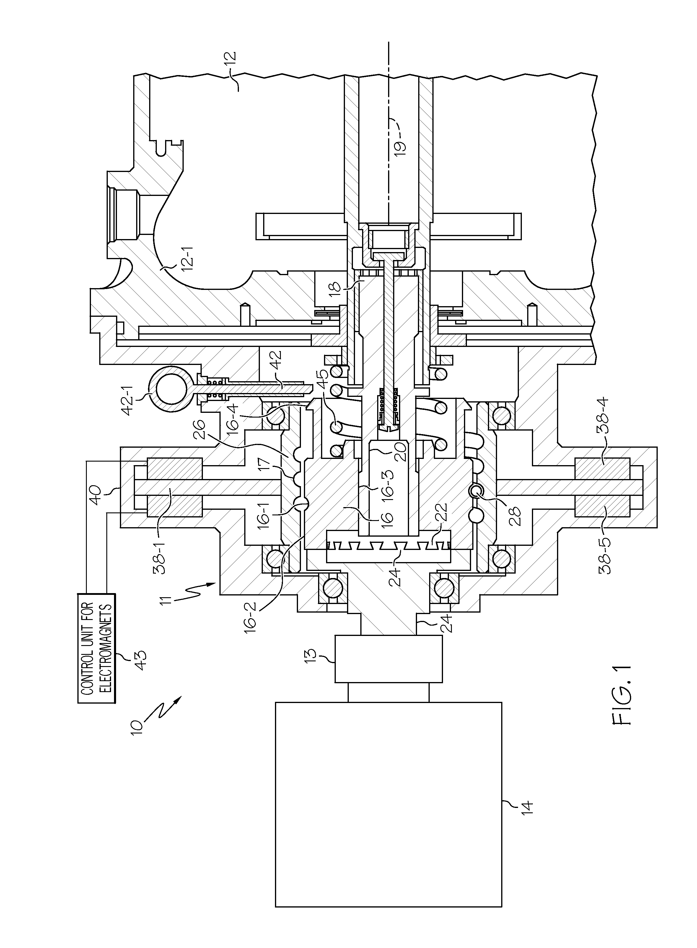
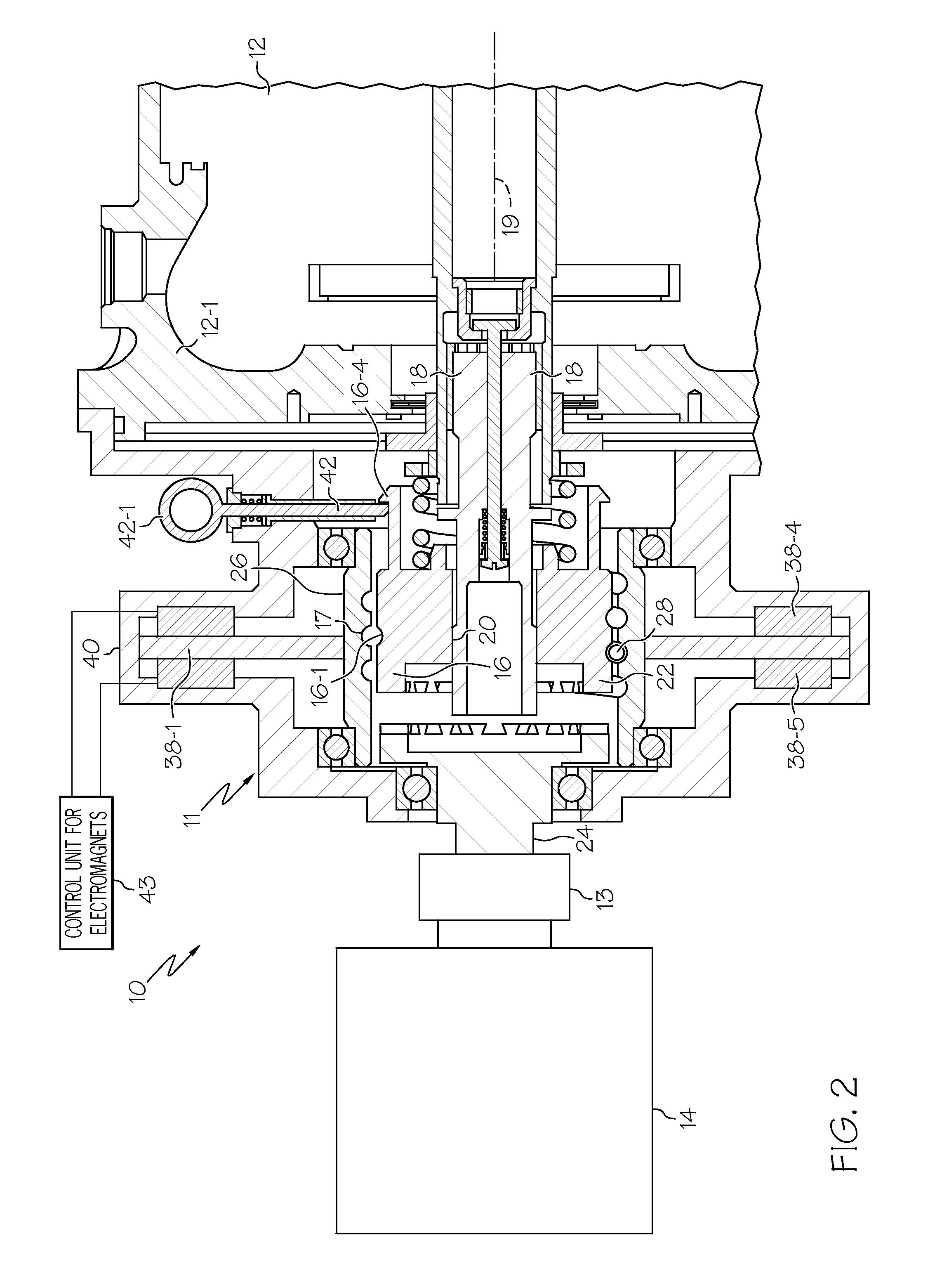
[0023]The following detailed description is of the best currently contemplated modes of carrying out the invention. The description is not to be taken in a limiting sense, but is made merely for the purpose of illustrating the general principles of the invention, since the scope of the invention is best defined by the appended claims.

[0024]The present invention generally provides a disengagement assembly for a rotating machine, such as an aircraft generator, for disengaging the generator from an engine or gear box. Typically the drive shaft of the generator may be rotating and operatively engaged to the drive shaft of the gear box. When the generator is not working properly, for example in an aircraft, the disengagement assembly may allow a pilot to disengage the generator from the gear box. A disengagement assembly may comprise an axially displaceable engagement member. Axial displacement may occur upon application of braking force on a rotating member of the disengagement assembly...


PUM


Abstract

A disengagement assembly for disengaging a generator from an engine or gear box may include an inner ball screw having helical threading on an outer surface thereof and surrounding and operatively engaged to a rotating generator drive shaft to cause rotation of the inner ball screw, the inner ball screw may have interlockable teeth engaged to corresponding teeth of the gear box drive shaft. An outer ball screw may surround and may normally rotate with the inner ball screw. A helical ball track may be formed between the inner and outer ball screws. An eddy current brake may slow or stop rotation of the outer ball screw so that the inner ball screw may rotate relative to the outer ball screw and slide axially toward a lock thereby disengaging the generator from the engine.

Description

CROSS-REFERENCE TO RELATED APPLICATIONS[0001]The present application is related to U.S. patent application Ser. No. 11 / 848,123, filed Aug. 31, 2007BACKGROUND OF THE INVENTION[0002]The present invention generally relates to apparatus and methods for disengaging generators and other rotating machines from a prime mover and, more particularly, to apparatus and methods of disengaging an aircraft generator from an engine or gear box to prevent damage to the engine or gear box.[0003]In the aerospace industry, aircraft receive electric power from generators. The generators may be coupled to the main engine or to auxiliary power units through a gear box. Known designs of generators have a generator drive shaft that includes some kind of shear section that is based on safe operational capability of the gearbox. In the event that the generator malfunctions, this shear section operates and protects the gear box from continuing to rotate under an unacceptable load from a malfunctioning generato...

Claims


Application Information

Patent Timeline
Patent Type & Authority Applications(United States)
IPC IPC(8): F16D27/09H02P15/00
CPCF16D2027/008F16D27/118
Inventor BURKE, DAVID W.GUZMAN LOPEZ, MIGUEL A.MACEDA, ARTURO
Owner HONEYWELL INT INC
Why Eureka
Try Eureka