Test method and apparatus for spark plug ceramic insulator

a technology of ceramic insulators and test methods, which is applied in the direction of spark plugs, instruments, machines/engines, etc., can solve the problems of flashover rather than the spark discharge, the insulating properties of ceramic insulators, and the failure to secure a sufficient detection accuracy

Active Publication Date: 2009-09-10
NGK SPARK PLUG CO LTD
View PDF17 Cites 20 Cited by
  • Summary
  • Abstract
  • Description
  • Claims
  • Application Information

AI Technical Summary

Benefits of technology

[0008]In view of the above conventional circumstances, it is therefore an object of the present invention to provide a tes

Problems solved by technology

As the thickness of the ceramic insulator becomes decreased for diameter reduction of the spark plug, the insulating properties of the ceramic insulator may so deteriorate that the above conventional test method could fail to secure a sufficient accuracy of detection of the presence or absence of the defect in the ceramic insulator.
Depending on the test conditions e.g. the positions of the first and second electrodes and the thickness of the ceramic insulator, the application of such a high voltage difference may result in the flashover rather than the

Method used


Image

  • Test method and apparatus for spark plug ceramic insulator
  • Test method and apparatus for spark plug ceramic insulator
  • Test method and apparatus for spark plug ceramic insulator

Examples


first embodiment

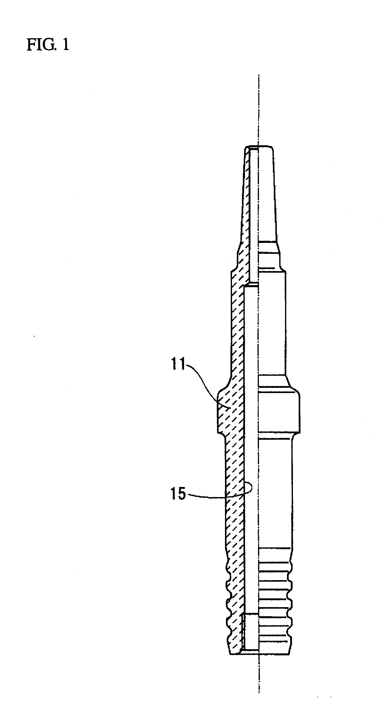
[0021]In the first embodiment, the presence or absence of a defect in the ceramic insulator 11 is detected by the following test.

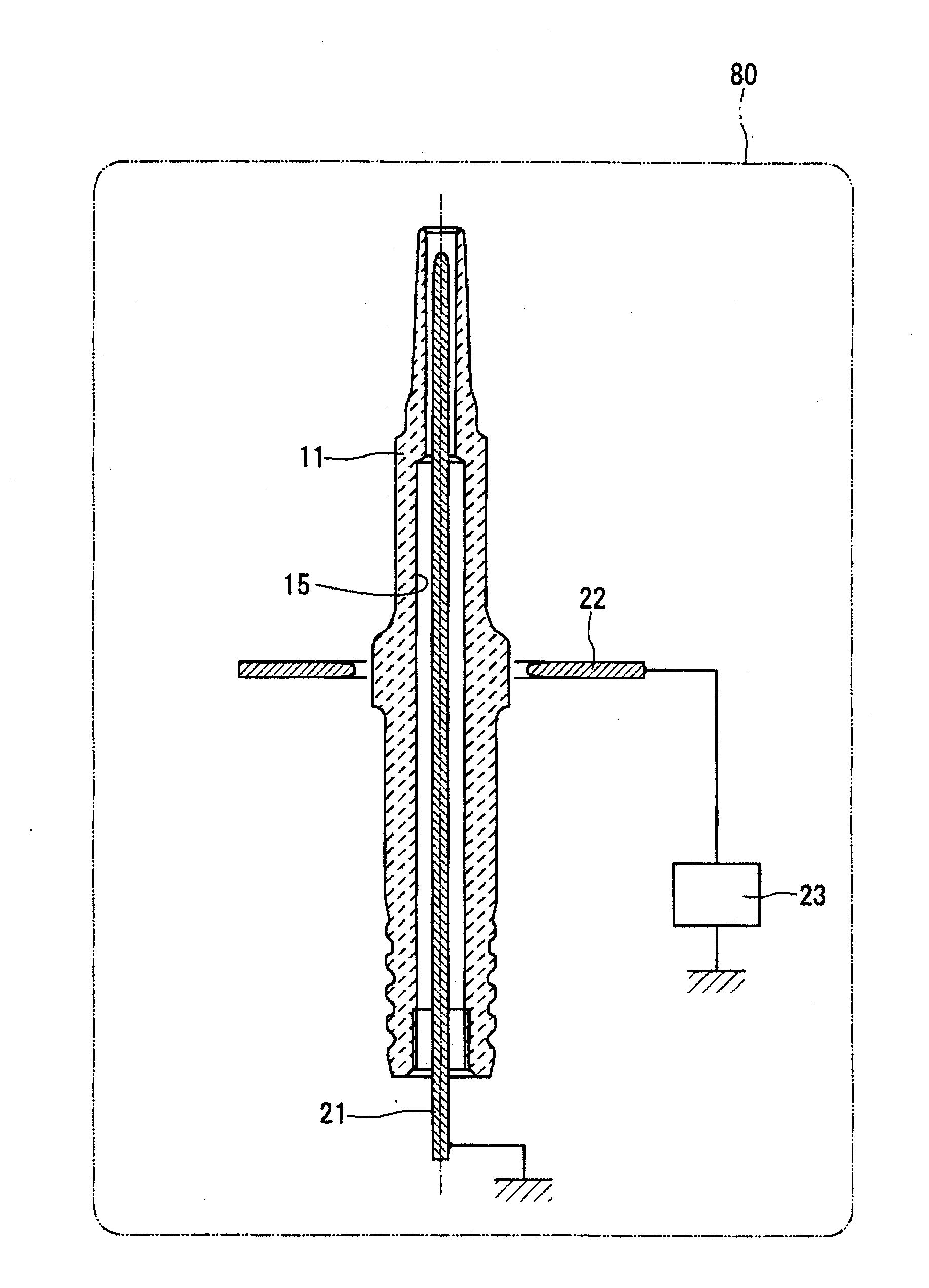
[0022]In the first test process, a rod-shaped first electrode 21 and an elongated cross-section annular second electrode 22 are placed by inserting the first electrode 21 in the inner through hole 15 of the ceramic insulator 11 and arranging the second electrode 22 on the outer peripheral side of the ceramic insulator 11 as shown in FIG. 3. The first electrode 21 and the second electrode 22 are also connected to a ground and a power source 23, respectively. The first electrode 21 and the second electrode 22 may alternatively be connected to the power source 23 and the ground, respectively. Herein, the power source 23 functions as a defect development means (first voltage application means) for developing a potential defect in the ceramic insulator 11 in combination with the first electrode 21 and the second electrode 22.

[0023]Then, a first voltage V1 is ap...

second embodiment

[0042]In the second embodiment, a plurality of ceramic insulators 11 can be tested simultaneously by means of a test apparatus 25. Herein, explanations of the same configurations and effects thereof as in the first embodiment will be omitted.

[0043]The test apparatus 25 has first electrodes 21d, a second electrode 22d and a power source 23d. The second electrode 22d is a mesh-shaped plate having multiple openings 22e throughout its length and breadth. The first electrodes 21d are rod-shaped and inserted through the centers of the openings 22e so as to correspond to the ceramic insulators 11, respectively. Each of the first electrodes 21d is connected to a ground. The second electrode 22d is connected to a power source 23d. The first electrodes 21d and the second electrode 22d may alternatively be connected to the power source 23d and the ground, respectively. The test apparatus 25 can be thus simplified by using the power supply circuit 23d common to the multiple electrode members.

[0...


PUM


Abstract

A test method for a spark plug ceramic insulator includes placing a first electrode in an inner hole of the ceramic insulator and placing a second electrode on an outer peripheral side of the ceramic insulator, developing a defect in the ceramic insulator by the application of a first voltage onto the ceramic insulator between the first and second electrodes and detecting the defect in the ceramic insulator by the application of a second voltage, which is lower than a flashover voltage that causes a flashover of the ceramic insulator, onto the ceramic insulator between the first and second electrodes.

Description

BACKGROUND OF THE INVENTION[0001]The present invention relates to a test method and apparatus for a spark plug ceramic insulator.[0002]Patent Publication 1 discloses a method for testing a spark plug ceramic insulator. This test method enables detection of the presence or absence of a defect in the spark plug ceramic insulator by the passage of an electric current between a first electrode placed in an inner hole of the ceramic insulator and a second electrode placed on an outer peripheral side of the ceramic insulator. More specifically, the test method includes the steps of generating a spark discharge through the application of a voltage between the first and second electrodes, allowing a path identification means to identify whether the spark discharge pass through an open end of the inner hole of the ceramic insulator and allowing a judgment means to judge the presence or absence of a defect in the ceramic insulator according to the identification result of the path identificat...

Claims


Application Information

Patent Timeline
IPC IPC(8): G01M19/02H01T13/58
CPCH01T13/58
Inventor HONDA, TOSHITAKATANABE, HIROYUKI
Owner NGK SPARK PLUG CO LTD
Why Eureka
Try Eureka