Ruggedized, self aligning, sliding air seal for removable electronic units

Active Publication Date: 2009-09-10
NORTHROP GRUMMAN SYST CORP
View PDF40 Cites 5 Cited by
  • Summary
  • Abstract
  • Description
  • Claims
  • Application Information

AI Technical Summary

Benefits of technology

[0017]The guide system of the present invention has two surfaces extending beyond the sealing surface of the electronics module providing protection for that sealing surface from objects that could damage the surface. These extensions provide a physical stop that prevents large objects from striking the sealing surface. In addition, the guides are extended so that they are a constant distance from the electronics module thus reducing the “rocking” that jammed the prior known sealing methods for printed circuit module

Problems solved by technology

Such leakage can have drastic effect on the system's thermal performance and overall reliability.
This has proven to be a difficult method to manufacture the seal.
The known systems for air cooling of removable electronic units utilize difficult to m

Method used


Image

  • Ruggedized, self aligning, sliding air seal for removable electronic units
  • Ruggedized, self aligning, sliding air seal for removable electronic units
  • Ruggedized, self aligning, sliding air seal for removable electronic units

Examples


Example

[0029]So that the manner in which the above recited features, advantages and objects of the present invention are attained can be understood in detail, more particular description of the invention, briefly summarized above, may be had by reference to the embodiment thereof that is illustrated in the appended drawings. In all the drawings, identical numbers represent the same elements.

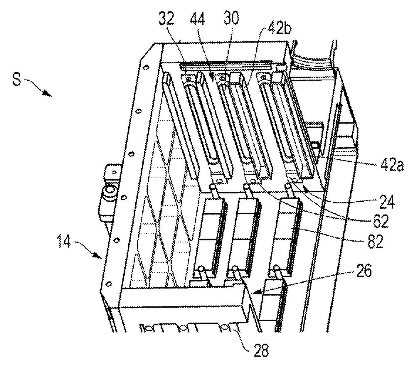
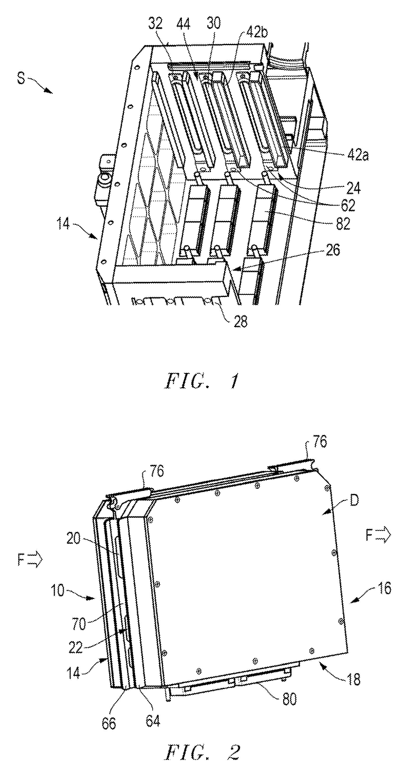
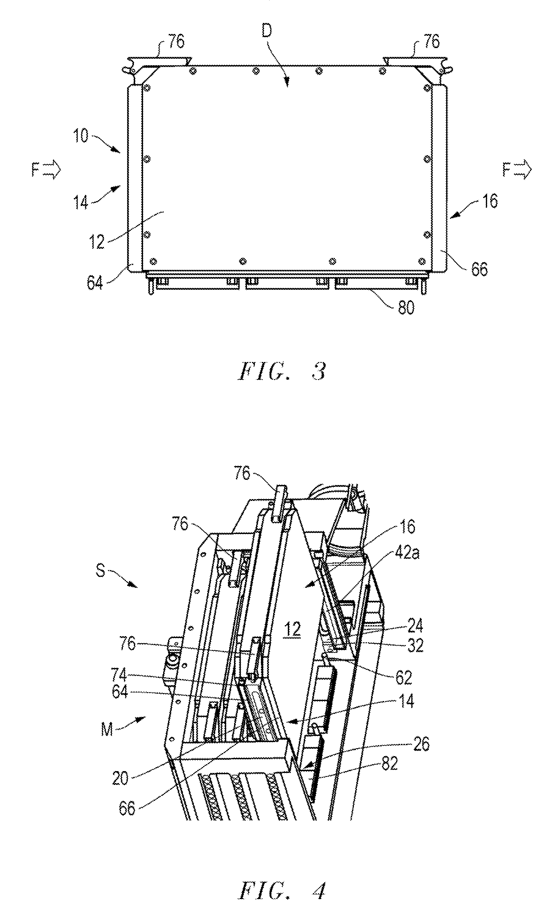
[0030]An electronics housing system S adapted for electronic devices D, such as radios, radars, transmitters, and the like, includes a main chassis unit or electronics rack M and at least one compatible and controllably removable module assembly 10 mountable with the base unit or electronic rack M for supporting electronic circuitry components, such as a printed circuit board 78, electrically or electro-optically coupled with the base unit M with cooperating connectors 80 and 82.

[0031]The removable module assembly 10 has a main body 12 that generally includes two opposing, vertical mounting edges 14, 16...


PUM


Abstract

An electronics housing system (S) adapted for electronic devices (D) includes a main chassis unit (M) and at least one removable module (10) mountable with the base unit (M) for supporting electronic circuitry components electro-optically coupled with the base unit (M). The removable module assembly (10) has a main body (12) that includes two opposing mounting edges (14, 16) and a connection edge (18). At least one of the mounting edges (14, 16) of the removable mounting assembly (10) has an opening (20) to receive a cooling air flow (F) into an interior cavity (22) of the main body (12) of the removable module (10). The main chassis (M) has a pair of opposing module mounting assemblies (24, 26) to receive a removable module (10) between the opposing module mounting assemblies (24, 26). The electronics rack wall (24, 26) includes a removable seal plate (32) to provide an air seal.

Description

CROSS REFERENCE TO RELATED APPLICATIONS[0001]This application claims the benefit of U.S. Provisional Application Ser. No. 61 / 034,300, filed Mar. 6, 2008, entitled RUGGEDIZED, SELF ALIGNING, SLIDING AIR SEAL FOR REMOVABLE ELECTRONIC UNITS.BACKGROUND OF THE INVENTION[0002]1. Technical Field[0003]The invention relates to the field of air seals, and more particularly to an air seal and retention system between an equipment housing and a removable module to deliver cooling air across or through electrical components mounted with the removable module.[0004]2. Background Art[0005]High power dissipating electronic assemblies require cooling air to be directed through a compact heat exchanger. This usually consists of a pair of printed circuit boards which may be bonded, or more likely fastened together by means of a frame positioned between the two modules. It is necessary to provide a reliable seal at each end of these modules to prevent leakage of any cooling air between the electronics r...

Claims


Application Information

Patent Timeline
IPC IPC(8): H05K7/20
CPCH05K7/20563
Inventor BIEMER, MICHAEL G.KONSOWSKI, STEPHEN C.HAAS, TIFFANIKRYWICKI, JASON
Owner NORTHROP GRUMMAN SYST CORP
Why Eureka
Try Eureka