
Analogue Beamforming

a technology of analog beams and beam switching, applied in the field of analog beam forming and beam switching in networks, can solve the problems of not having a zone to support abf, and the optimal use of analog beams by multiple antenna elements

Inactive Publication Date: 2009-09-10
MITSUBISHI ELECTRIC RES LAB INC
View PDF6 Cites 52 Cited by
  • Summary
  • Abstract
  • Description
  • Claims
  • Application Information

AI Technical Summary

Problems solved by technology

Analog beam forming (ABF) is not the theoretic optimal way of using multiple antenna elements.
However, that frame does not have zones to support ABF.

Method used


Image

  • Analogue Beamforming
  • Analogue Beamforming
  • Analogue Beamforming

Examples


Embodiment Construction

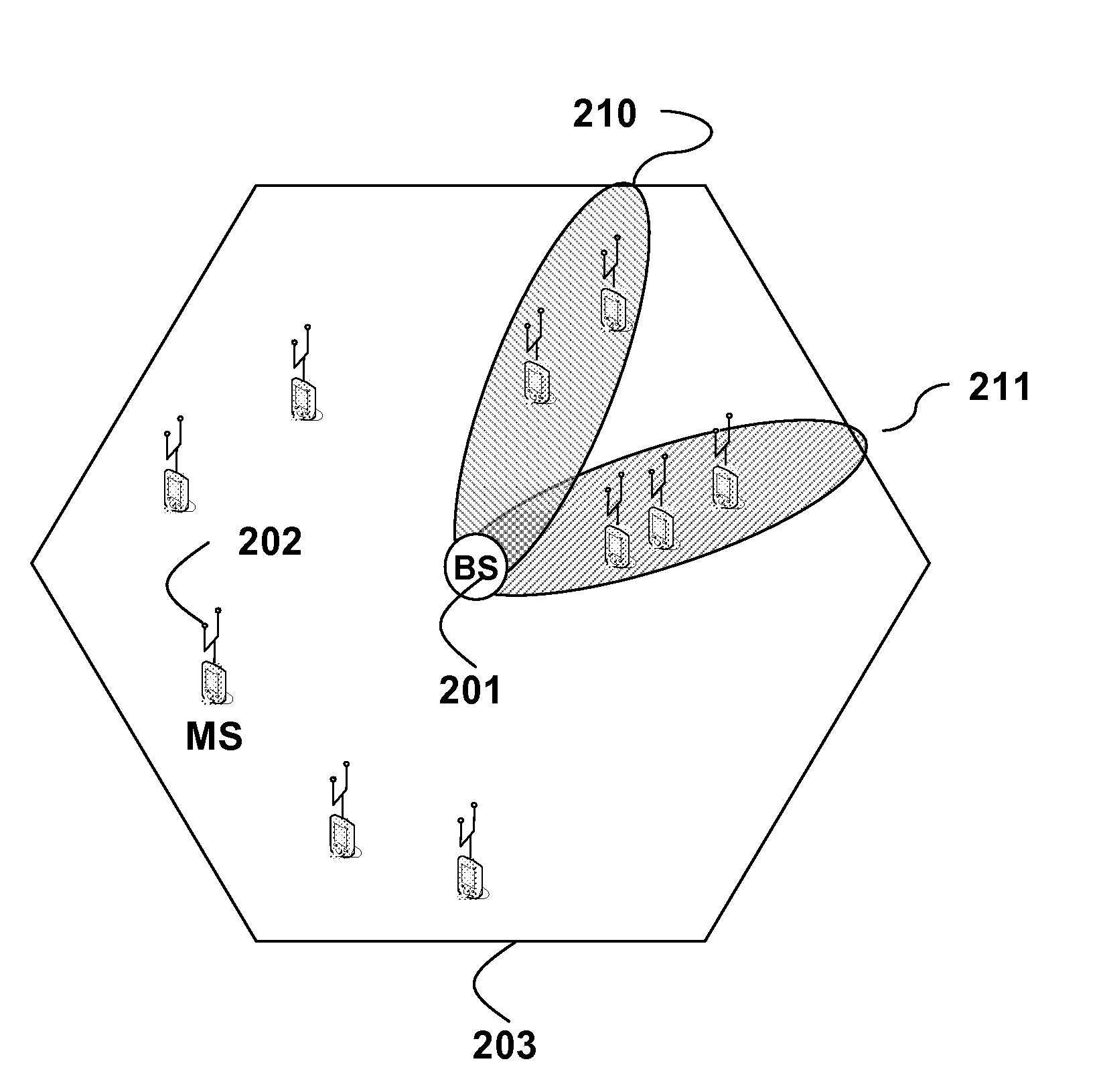
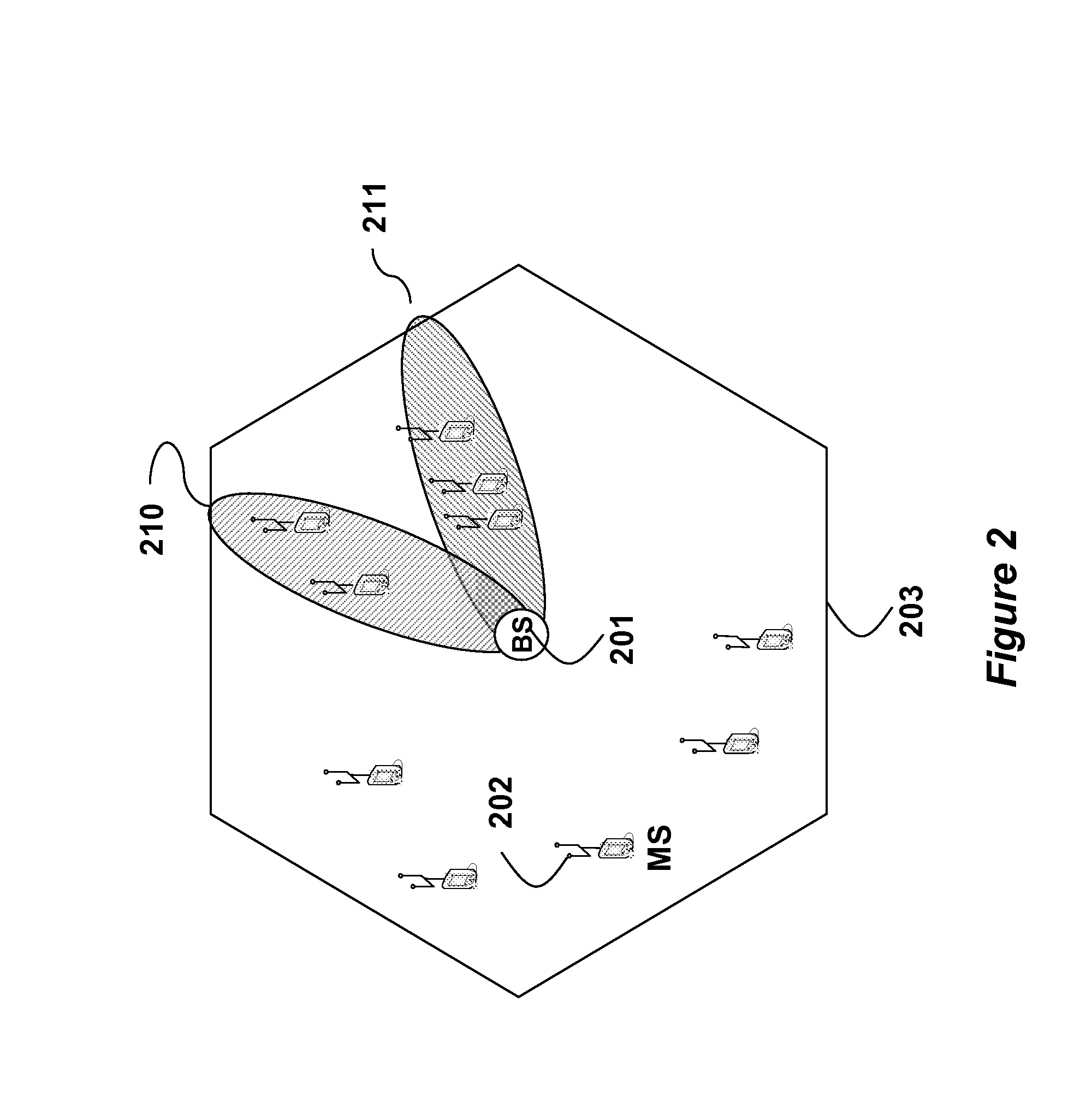
[0023]FIG. 2 shows a wireless network with a base station (BS) 201, and a set of mobile stations (MS) 202 according to embodiments of our invention. The BS can form beams 210-211 within the cell 203 using a linear antenna array concatenated with a Butler matrix, see U.S. Patent Application 20060104197, “Method and system for economical beam forming in a radio communication system.”

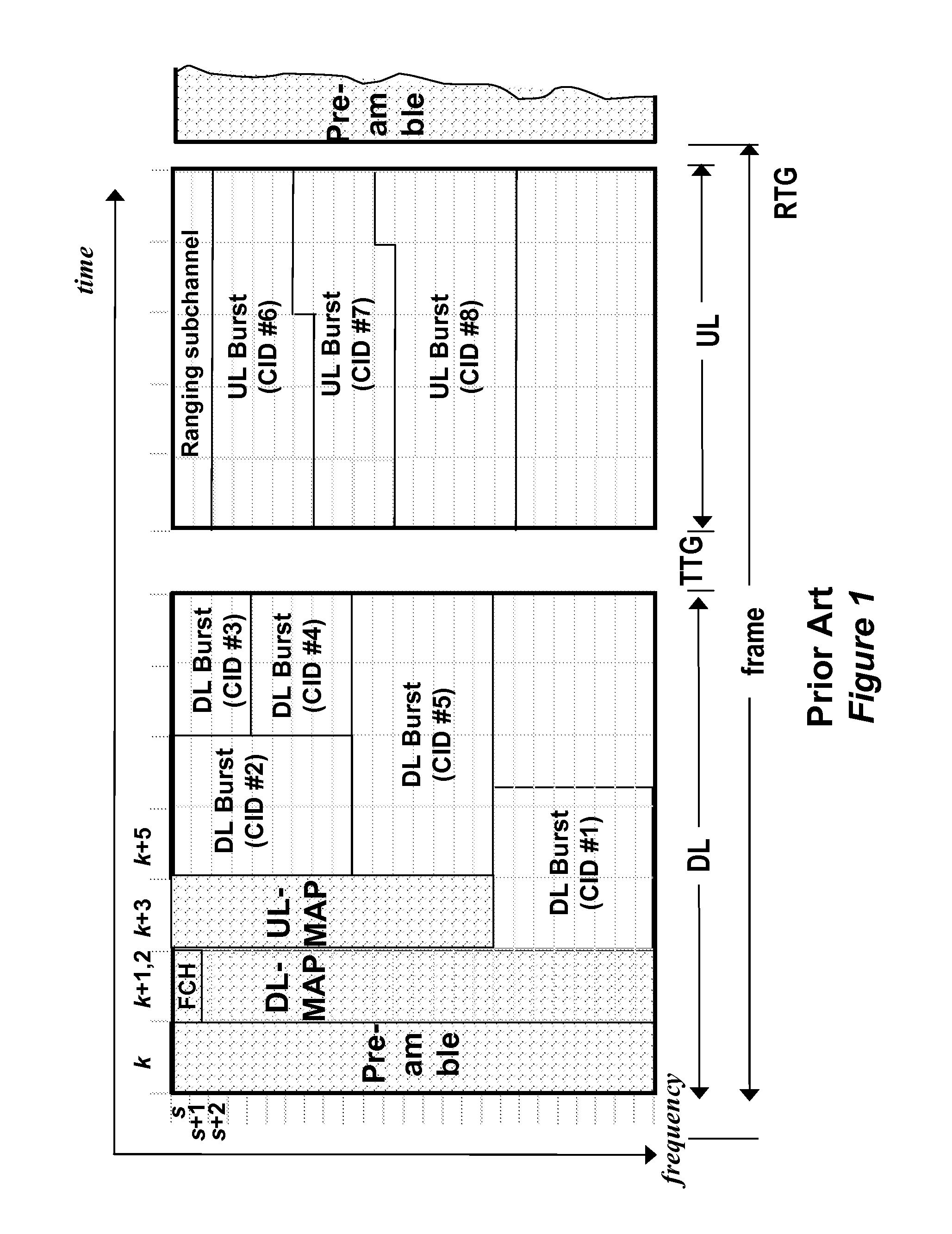
[0024]Analog beam forming (ABF) requires that we define new zones in the superframe structure for the down link (DL) and the up link (UL). A zone is a time division duplexing technique that allows multiple transmission formats in the same DL and UL.

[0025]By partitioning the DL into multiple zones, the MS in different zones can be handled sequentially. Each ABF zone corresponds to a transmission interval in the DL, where a particular beam is active at the BS. Thus, the MS within the geographic coverage area of the active beam are grouped into an active set, and served during the corresponding zones.

[0026]Th...


PUM


Abstract

An orthogonal frequency division multiple access (OFDMA) network including a base station (BS) associated with a set of mobile stations (MS) in a cell. The set of MS are grouped into sets of active MS, wherein each set of active MS corresponds to a beam formed at the BS. The BS transmits a down link (DL) subframe using analog beam forming (ABF), wherein the DL subframe has one ABF zone for each set of active MS and each corresponding beam.

Description

RELATED APPLICATION[0001]This patent application claims priority to Provisional Application 61 / 035,123, “Analogue Beamforming,” filed by Kuze et al. on Mar. 10, 2008, incorporated herein by reference.FIELD OF THE INVENTION[0002]This invention relates generally to wireless networks, and more particularly to analog beam forming and beam switching in networks according to the IEEE 802.16m standard.BACKGROUND OF THE INVENTION[0003]One object of networks designed according to the Worldwide Interoperability for Microwave Access (WiMAX) standard is to improve a spectral efficiency of networks, while keeping the cost of deployments to a minimum. Fixed WiMAX is based on the IEEE 802.16d standard, and mobile WiMAX on the IEEE 802.16e standard.[0004]One way to do this is to use analog beam forming (ABF). The BS can switch arbitrarily through the available beams on the up link and the down link and communicates with the MS located in the active beams. The range of the cell is extended by the be...

Claims


Application Information

Patent Timeline
Patent Type & Authority Applications(United States)
IPC IPC(8): H04B7/212H04W4/00
CPCH04B7/043H04W16/28H04B7/0671H04B7/0634
Inventor TAO, ZHIFENGMOLISCH, ANDREAS F.ORLIK, PHILIP V.ZHANG, JINYUNKUZE, TOSHIYUKI
Owner MITSUBISHI ELECTRIC RES LAB INC
Learn More