Low cost threat detection sensor

a low-cost, threat-detecting technology, applied in the direction of optical radiation measurement, distance measurement, instruments, etc., can solve the problems of limiting the field limiting the and limiting the range of vision and response time, so as to achieve the effect of reducing the effectiveness or sensitivity of the detector

Active Publication Date: 2009-09-10
LOCKHEED MARTIN CORP
View PDF10 Cites 18 Cited by
  • Summary
  • Abstract
  • Description
  • Claims
  • Application Information

AI Technical Summary

Benefits of technology

[0011]A cylindrical window allows the sensor a 360-degree field of view, giving panoramic line-of-sight coverage without requiring any mechanical or electrical steering mechanism. Refractive optics consolidate the incoming light and direct it to a filtering device configured to remove all but a certain wavelength of light. This wavelength is known to correspond to light produced by the burning of substances such as potassium and other elements and compounds typically found in the propellants of rocket-propelled munitions.
[0012]In one embodiment of the present invention, a reflector mounted to the top of the cylindrical window governs the vertical field of view (FOV) of the sensor, determining how far above and below the horizon the device can “see.” This enables the device to ignore devices such as flares, passing jets, and other possible sources of high-altitude interference without compromising the effectiveness or sensitivity of the detector. This is accomplished by ensuring that the window and reflector are shaped such that light may not pass through the refractive optics portion of the sensor without first entering the cylindrical window and reflecting off the reflector. This allows for control over the vertical field of view by changing the shape of the reflector.
[0014]An embodiment of the invention may be equipped with a Magneto-Optical filter designed to reject all light impinging on it except for the narrow wavelengths corresponding to potassium, which is a widely used component in rocket propellants. This allows for the identification of small rocket launches without requiring hardware components to track movement or image a scene in a spectrum such as infrared or ultra-violet.
[0016]Embodiments of the present invention may be configured so that even after filtering and intensification, the remaining light signal retains a frame of reference to the scene as originally imaged. This enables the sensor to determine the location of the detected rocket launch within the imaged scene.

Problems solved by technology

Current systems capable of detecting firing of such portable, shoulder-fired weapons are costly and complex.
These systems typically require multiple sensors and complex mechanical or electrical steering systems to accomplish 360-degree coverage and accurate detection.
Further, the need for a system to be steered means that it cannot simultaneously provide detection in all directions, limiting its field of vision and response time.
Limited response time, while perhaps only amounting to fractions of a second, is a serious drawback when the detected threats are traveling towards a target at hundreds of miles per hour.
The cost and weight of such systems also pose difficulties to their production and field use.
Multiple sensors and steering mechanisms render these systems expensive and heavy, meaning that production of them may be limited, and that they are most likely to be deployed onto large vehicles such as tanks and aircraft, or affixed to permanent structures such as buildings or antenna towers.

Method used


Image

  • Low cost threat detection sensor
  • Low cost threat detection sensor
  • Low cost threat detection sensor

Examples


Embodiment Construction

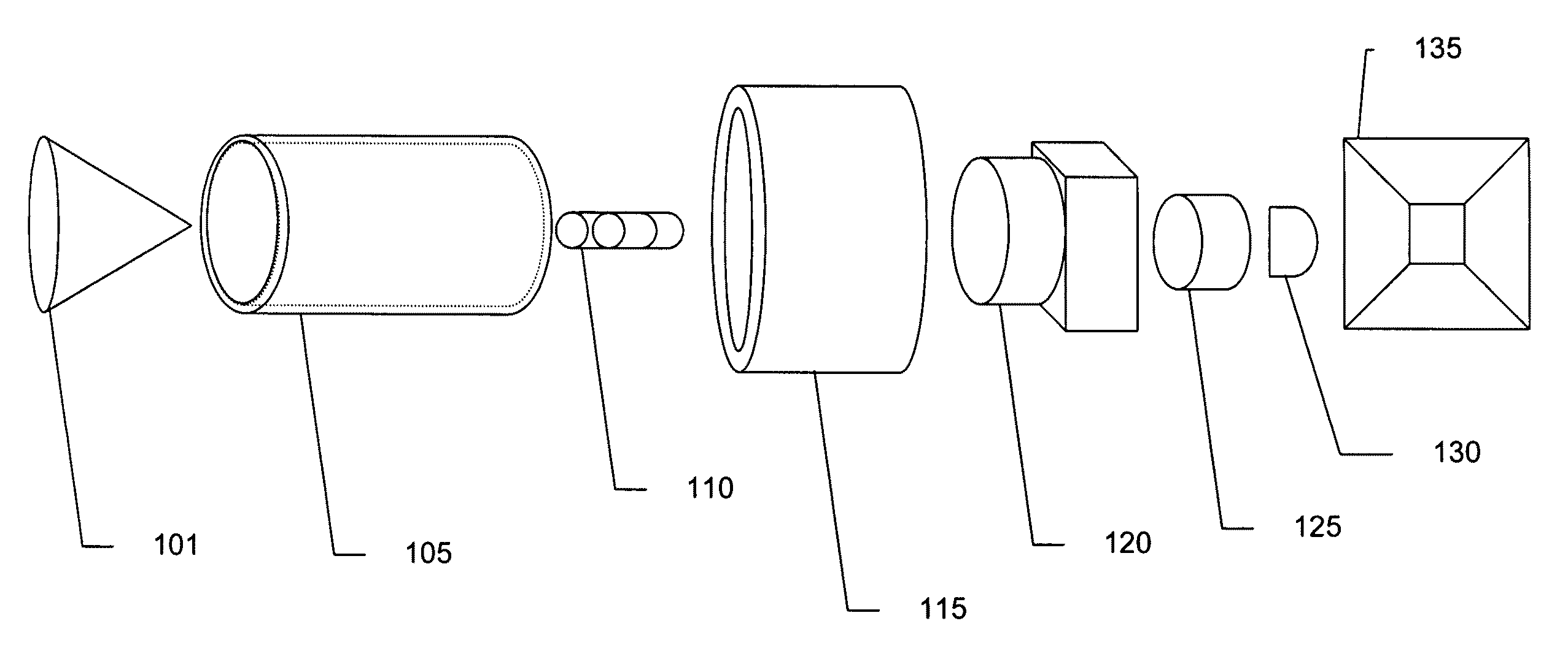
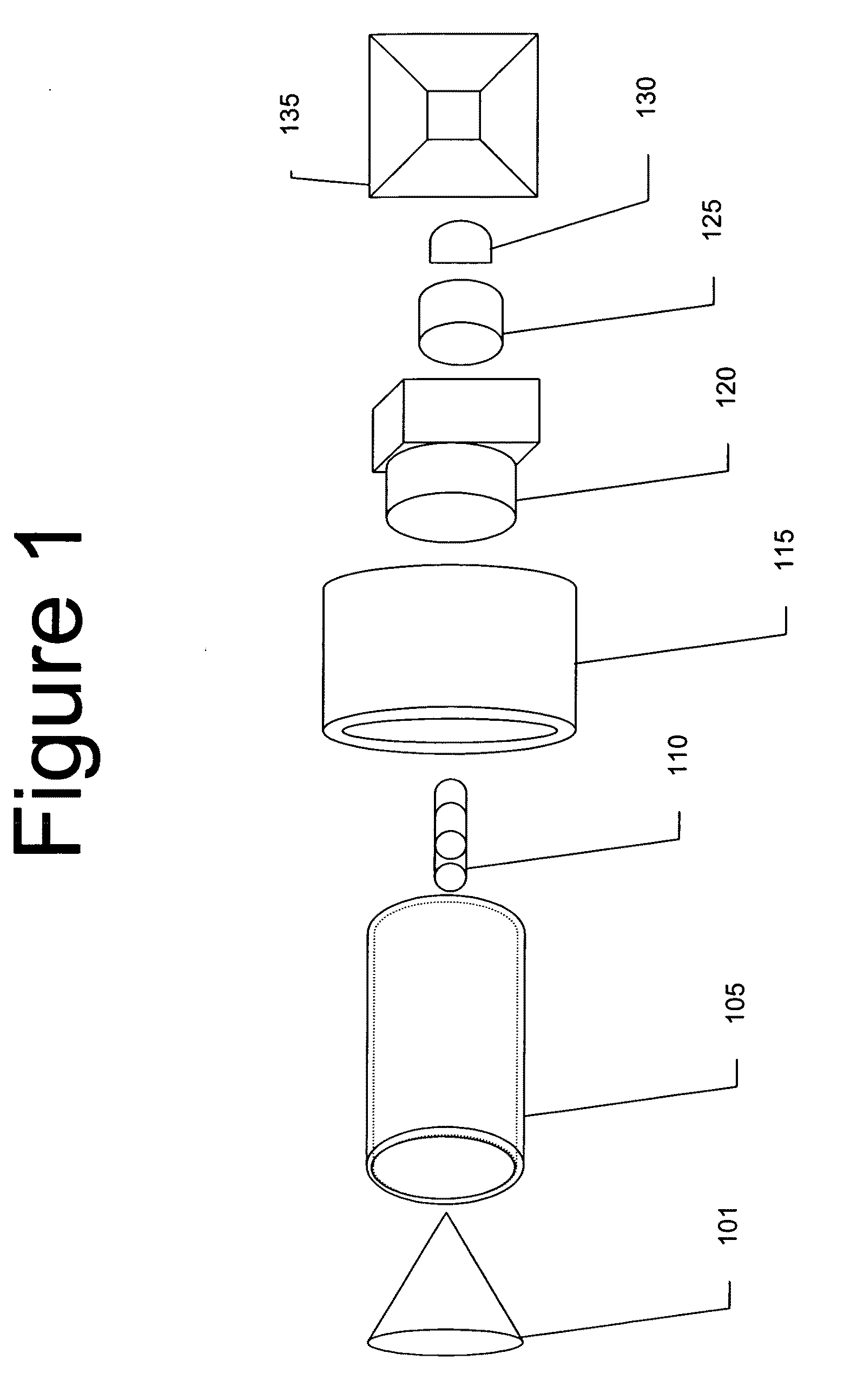
[0025]The following detailed description of the invention refers to the accompanying drawings. The same reference numbers in different drawings identify the same or similar elements. Also, the following detailed description does not limit the invention. Instead, the scope of the invention is defined by the appended claims and equivalents thereof.

[0026]Current sensor systems available for threat detection are typically in the form of mechanically or electrically scanned radar or cryogenically cooled detectors. The present invention has the advantages of requiring no mechanical or electrical scanning, or any form of cryogenic cooling. This reduces both weight and component cost as the need for mechanical actuators, complex electronics, and cooling / refrigeration systems is reduced.

[0027]Although a forward-looking detection device can be rotated for 360 degree imaging or utilize multiple sensors to cover 360 degrees these configurations introduce a host of complexities readily avoided b...


PUM


Abstract

The present invention addresses issues of cost and weight that prevent other threat detection systems intended to detect and identify locations of incoming munitions fire such as RPGs, anti-tank missiles, and other such weapons, from being used more broadly.The invention consists of a portable, optical sensor that has a 360-degree horizontal field of view and a selectable vertical field of view that can cover up to 90 degrees. An embodiment of the invention is meant for use and transport by an individual or group of individuals, and does not require significant support electronics or power supplies in excess of a typical car-battery in size and weight. Other embodiments may be vehicle mounted, or may be further enhanced to work with other detection or response systems.

Description

BACKGROUND OF THE INVENTION[0001]1. Field of the Invention[0002]The present invention relates generally to the detection of incoming munitions fire and, more particularly, to methods and devices for detecting incoming fuel-burning munitions such as rockets and missiles.[0003]2. Description of Related Art[0004]Detection of incoming threats is a goal of ever-increasing importance in any battlefield situation. The ability to detect, prepare for, and take measures against incoming weapons fire is a critical ability for any military forces in a hostile environment.[0005]Threat detection technologies have generally evolved as weapons have become progressively more powerful, more portable, and more readily concealable. Given the ability of military or paramilitary forces, or even civilians, to acquire and use weapons such as Stinger missiles, rocket-propelled grenades (RPGs), or M72 anti-tank rockets, the need for rapid detection of the use of such weapons becomes an ever-more essential de...

Claims


Application Information

Patent Timeline
Patent Type & Authority Applications(United States)
IPC IPC(8): G06K9/40G01T1/00
CPCG01S3/784F41J5/02
Inventor WARREN, MICHAELAMON, MAXSANDH JR., ROBERT F.
Owner LOCKHEED MARTIN CORP
Why Eureka
Try Eureka