Retrodrill System

a rerodrill system and bone tunnel technology, applied in bone drill guides, medical science, surgery, etc., can solve the problem that the flexible reamer that is currently produced cannot be easily made smaller than 7 mm

Inactive Publication Date: 2009-09-10
SMITH & NEPHEW INC
View PDF2 Cites 29 Cited by
  • Summary
  • Abstract
  • Description
  • Claims
  • Application Information

AI Technical Summary

Problems solved by technology

The flexible reamers that are currently prod

Method used


Image

  • Retrodrill System
  • Retrodrill System
  • Retrodrill System

Examples


Embodiment Construction

[0030]The following description of the preferred embodiment(s) is merely exemplary in nature and is in no way intended to limit the disclosure, its application, or uses.

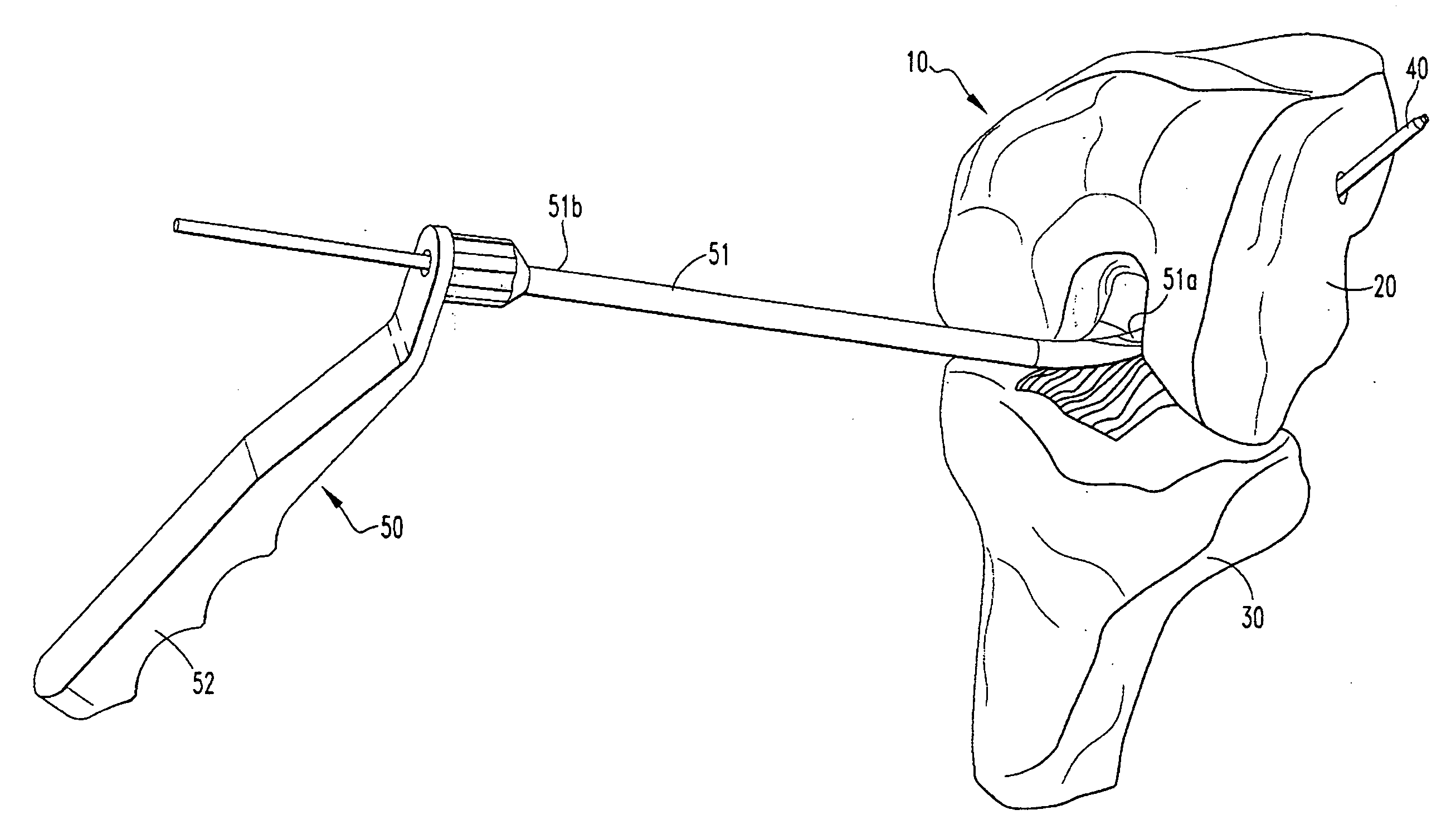
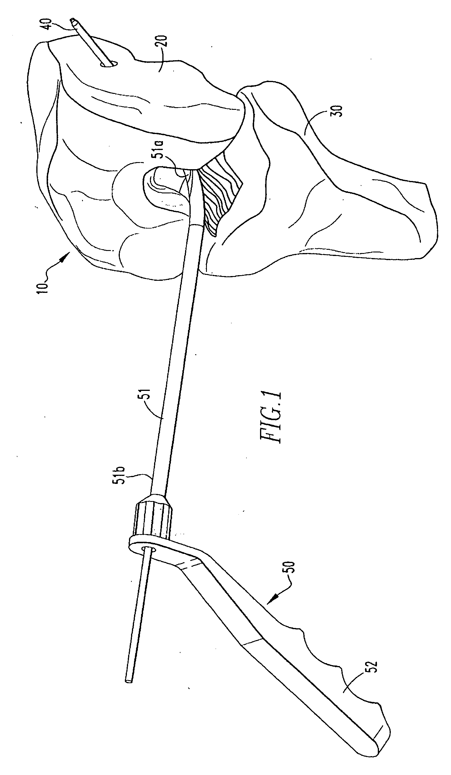
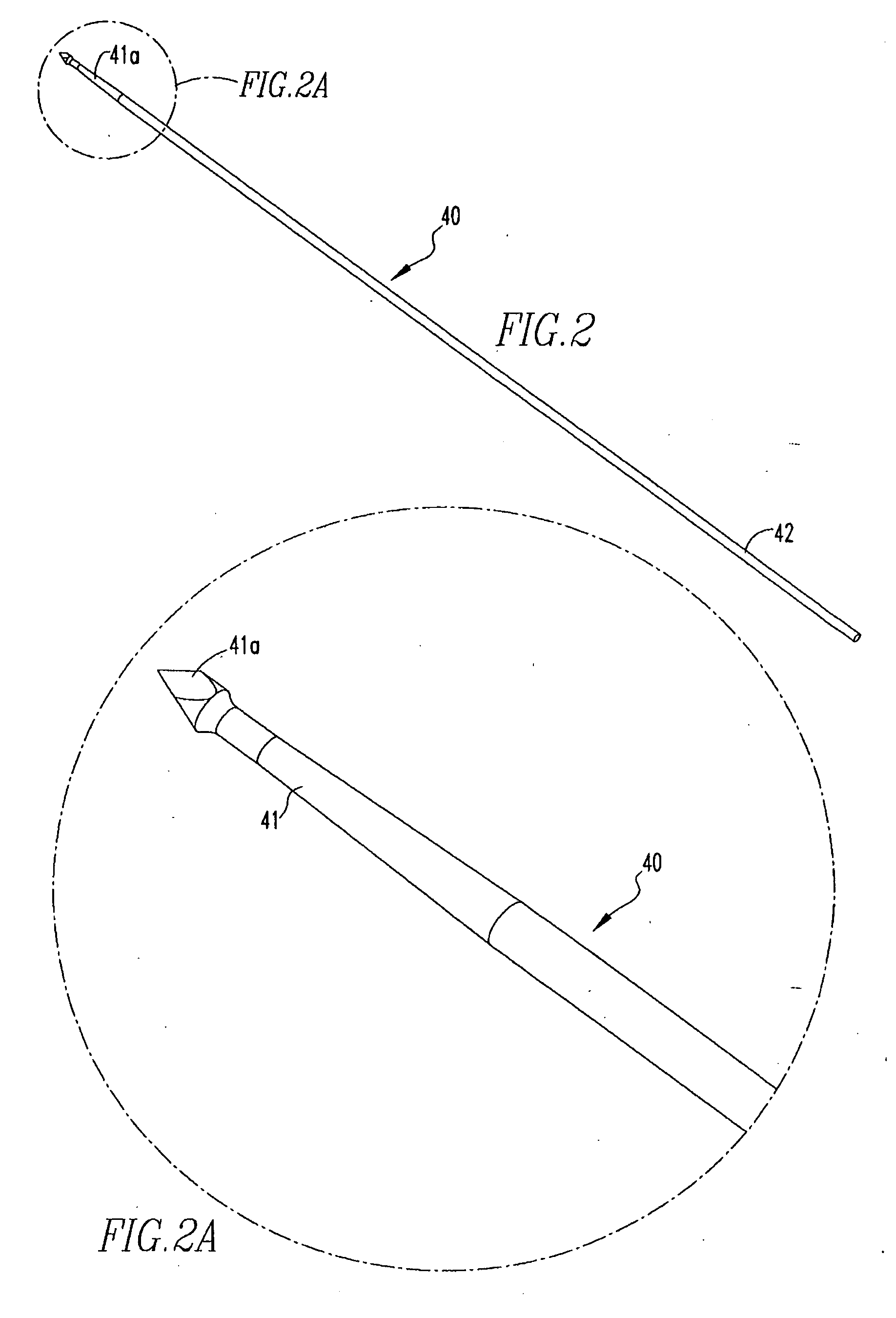
[0031]FIG. 1 shows a knee joint 10 including a femur 20 and a tibia 30, and specifically, insertion of a guide wire 40 into the femur 20 via use of a drill guide 50 and a drill (not shown). The guide wire 40 will be used, in combination with the drill, to drill a tunnel into the femur 20 in preparation for receipt of a tissue graft, as will be further described below. Prior to inserting the guide wire 40 into the femur 20, the surgeon views the femur 20 arthroscopically and determines the best location for inserting the guide wire 40. Subsequently, the surgeon inserts a cannulated shaft 51 of the guide 50 into the joint 10 and positions a distal end 51a of the shaft 51 against the femur 20. The shaft 51 includes the distal end 51a and a proximal end 51b. The distal end 51a is curved and the proximal end 51b is couple...


PUM


Abstract

The present disclosure relates to a method of creating a bone tunnel during ligament reconstruction surgery. The method includes placing a guide wire through the femur, the guide wire having a first end portion including a pointed tip and a second end portion; placing a drill mechanism over the first end portion of the guide wire, the drill mechanism having a first end portion including a drill bit and a second end portion including an attachment portion; coupling an adaptor assembly to the attachment portion, the adaptor assembly including a shaft; coupling a drill to the shaft and operating the drill to create a tunnel in the femur; coupling a drill bit assembly to the second end portion of the guide wire and locating the assembly against the drill bit of the attachment portion; and operating the drill to create a counter bore within the tunnel.

Description

CROSS-REFERENCE TO RELATED APPLICATIONS[0001]This application claims the benefit of U.S. Patent Application No. 61 / 034,189, filed Mar. 6, 2008, the disclosure of which is incorporated by reference in its entirety.BACKGROUND[0002]1. Field of Technology[0003]The present disclosure relates to the creation of bone tunnels during ligament reconstruction surgery, and more specifically, the creation of femoral bone tunnels.[0004]2. Related Art[0005]For torn knee ligament reconstruction, there has been an evolution in the anatomic femoral placement of the tissue graft. This can be accomplished by several methods all of which provide the ability to create a tunnel socket from the inside to the outside of the femur. Without hyperflexing the knee, a curved drilling path is needed to accomplish this procedure. A curved guide wire is first placed through the femur to act as a guide pin. An appropriate sized reamer is then advanced over the guide wire to create a drilled bone tunnel. A shortcomin...

Claims


Application Information

Patent Timeline
IPC IPC(8): A61B17/00A61B17/58
CPCA61B17/1617A61B17/1675A61B17/17A61B17/8897A61B17/1764A61B17/1714
Inventor BOURQUE, BERNARD J.FERRAGAMO, MICHAEL C.GRAF, BEN K.DAVIS, WILLIAM
Owner SMITH & NEPHEW INC
Why Eureka
Try Eureka