Method of simulating pneumatic tire based on finite element models

a pneumatic tire and finite element technology, applied in the field of simulating pneumatic tires based on finite element models, can solve the problems of high labor intensity and time-consuming, quadrilateral membrane elements failing to properly analyze the behavior of composite assemblies, simulating methods failing to sufficiently analyze the performance of tires with accuracy, etc., to achieve accurate analysis of pneumatic tire performance

Inactive Publication Date: 2009-09-10
YOKOHAMA RUBBER CO LTD
View PDF5 Cites 12 Cited by
  • Summary
  • Abstract
  • Description
  • Claims
  • Application Information

AI Technical Summary

Benefits of technology

[0006]It is an object of the present invention to provide a method of simulating a pneumatic ...

Problems solved by technology

Since the carcass or belt of a single tire includes more than thousand cords, the simulation needs vast computational efforts and hence is highly tedious and time-consuming to carry out.
The proposed simulating method, however, is disadvantageous in that as the cords of the composite assembly is modeled...

Method used


Image

  • Method of simulating pneumatic tire based on finite element models
  • Method of simulating pneumatic tire based on finite element models
  • Method of simulating pneumatic tire based on finite element models

Examples


Embodiment Construction

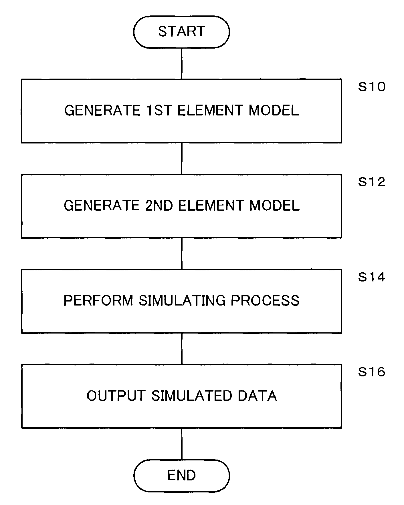
[0024]A method of simulating a pneumatic tire according to an embodiment of the present invention will be described in detail below with reference to the drawings.

[0025]First, a composite assembly (stiffener) of a tire and a process of modeling the composite assembly will be described below.

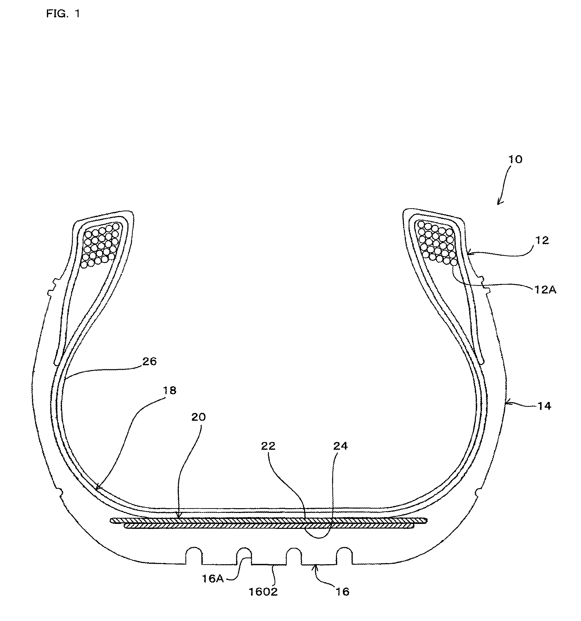
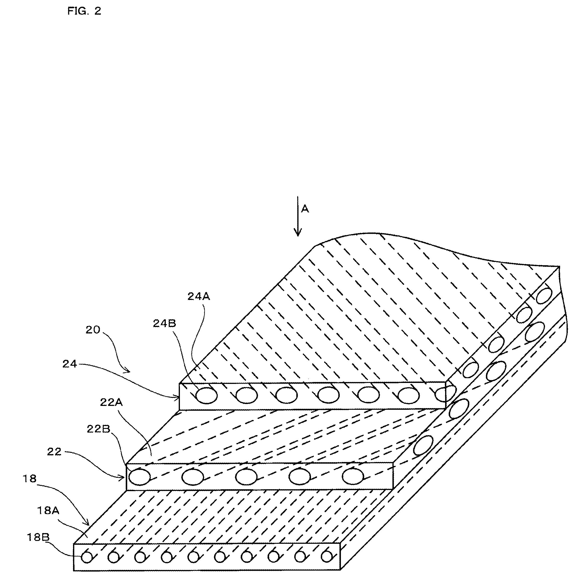
[0026]FIG. 1 is a transverse cross-sectional view of a pneumatic tire 10 taken along a plane extending through the central axis thereof. FIG. 2 is an enlarged fragmentary perspective view, partly in cross section, showing structural details of a composite assembly of a carcass and a belt of the pneumatic tire shown in FIG. 1. FIG. 3 is a plan view of the composite assembly as viewed in the direction of arrow A in FIG. 2.

[0027]As shown in FIG. 1, the tire 10 comprises a pair of laterally spaced beads 12, a pair of laterally spaced sidewalls 14, a tread 16, a carcass 18, and a belt 20. The carcass 18 and the belt 20 jointly serve as a composite assembly as described later.

[0028]The beads 12, which ...


PUM


Abstract

A pneumatic tire includes a composite assembly comprising a rubber web and a plurality of parallel cords embedded in the rubber web at spaced intervals in the circumferential directions of the pneumatic tire. The pneumatic tire is approximated with a finite element model generated by dividing the pneumatic tire into a plurality of finite elements and analyzing the finite element model according to a finite element process. A composite assembly element model is generated for the composite assembly by dividing the rubber web into rubber web elements as solid models and dividing the cords into cord elements as solid elements, according to the finite element process.

Description

FIELD OF THE INVENTION[0001]The present invention relates to a method of simulating a pneumatic tire based on finite element models.BACKGROUND ART[0002]There have been proposed in the art a variety of methods of simulating a pneumatic tire (also referred to simply as “tire”) by approximating the pneumatic tire with a finite element model which is generated by dividing the tire into a plurality of finite elements and analyzing the finite element model according to the finite element method.[0003]According to one of the proposed pneumatic tire simulating methods, a composite assembly (stiffener) of a belt and a carcass, each including a plurality of cords, among other components of the tire, is converted into a simplified model, rather than a faithful model (see JP No. 11-153520 A). Specifically, the cords are modeled into a quadrilateral membrane element with defined anisotropy, and the composite assembly is calculated as a continuous body whose cross-sectional shape remains the same...

Claims


Application Information

Patent Timeline
IPC IPC(8): G06G7/48G06F17/50
CPCB60C9/02B60C9/20B60C99/006G06F17/5095G06F17/5018G06F30/15G06F30/23
Inventor SETO, HIDEKIHANADA, RYOJI
Owner YOKOHAMA RUBBER CO LTD
Why Eureka
Try Eureka