
Ejector device and refrigeration cycle apparatus using the same

a technology of ejector device and nozzle, which is applied in the direction of lighting and heating apparatus, combustion types, refrigeration components, etc., can solve the problems of difficult stably improving the efficiency of nozzles, and achieve the effects of improving nozzle efficiency, improving ejector efficiency, and increasing the pressure of mixed refrigeran

Active Publication Date: 2009-09-17
DENSO CORP
View PDF11 Cites 44 Cited by
  • Summary
  • Abstract
  • Description
  • Claims
  • Application Information

AI Technical Summary

Benefits of technology

[0005]In view of the foregoing problems, it is an object of the present invention to provide an ejector device having a nozzle in which a nozzle efficiency can be stably improved even when gas-liquid two-phase refrigerant flows into a throat portion of the nozzle.
[0006]It is another objection of the present invention to provide a refrigeration cycle apparatus with an ejector device, in which a nozzle efficiency can be stably improved even when gas-liquid two-phase refrigerant flows into a throat portion of the nozzle while ejector efficiency can be improved.
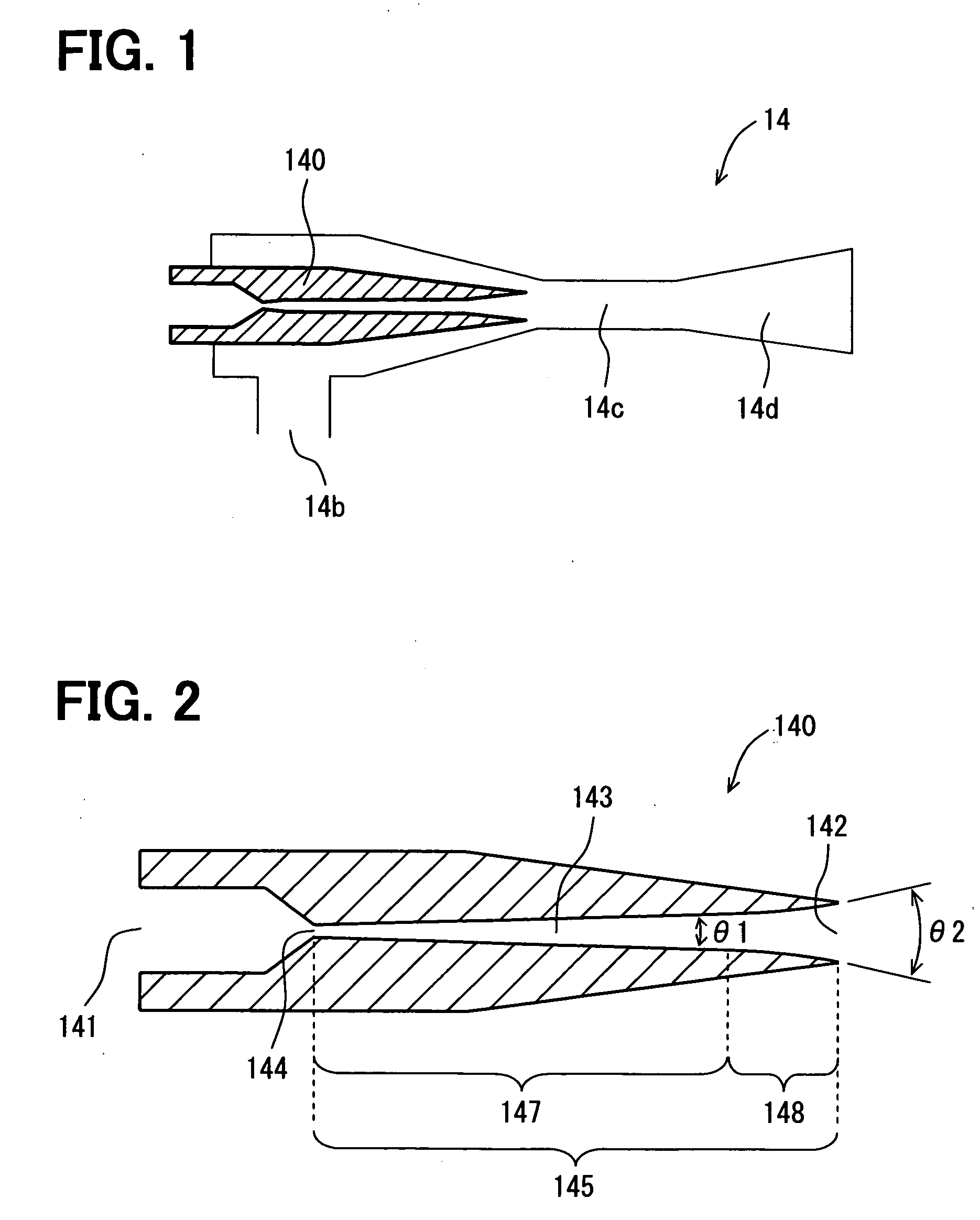
[0007]According to a first aspect of the present invention, an ejector device includes a nozzle having an inner wall surface defining a fluid passage extending from an inlet to a jet port of the nozzle. The fluid passage is a circular shape in a cross section perpendicular to an axial line of the fluid passage. The fluid passage has a throat portion at a position between the inlet and the jet port, at which a cross-sectional area of the fluid passage becomes smallest, and a passage expanding portion in which the cross-sectional area of the fluid passage is enlarged from the throat portion as toward downstream to decompress a fluid flowing into the throat portion. The passage expanding portion includes a middle portion in which the inner wall surface is expanded in a fluid flow direction by a first expanding angle, and an outlet portion from a downstream end of the middle portion to the jet port, in which the inner wall surface is expanded in the fluid flow direction by a second expanding angle that is larger than the first expanding angle. Accordingly, it is possible to increase an expanding ratio of the passage cross-sectional area of the outlet portion to be larger than an expending ratio of the passage cross-sectional area of the middle portion in the nozzle. As a result, the fluid can be easily accelerated in the passage expanding portion of the nozzle, thereby stably improving the nozzle efficiency even when gas-liquid two-phase refrigerant flows into the throat portion of the nozzle.

Problems solved by technology

However, in the ejector device described in JP 11-37577A, when gas-liquid two-phase refrigerant is introduced into the throat portion of the nozzle body, it is difficult to stably improve the nozzle efficiency.

Method used


Image

  • Ejector device and refrigeration cycle apparatus using the same
  • Ejector device and refrigeration cycle apparatus using the same
  • Ejector device and refrigeration cycle apparatus using the same

Examples


first embodiment

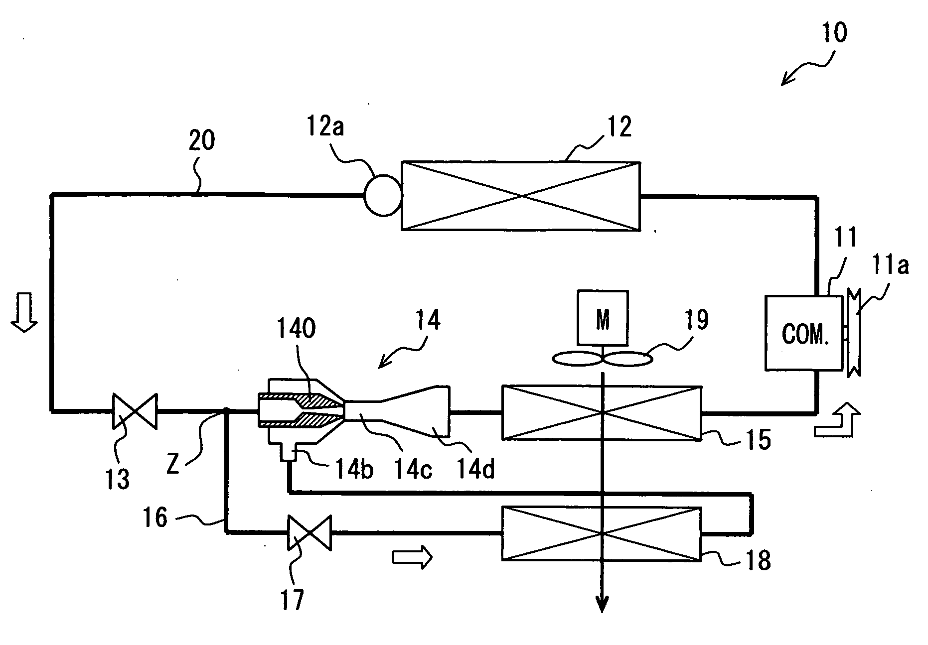
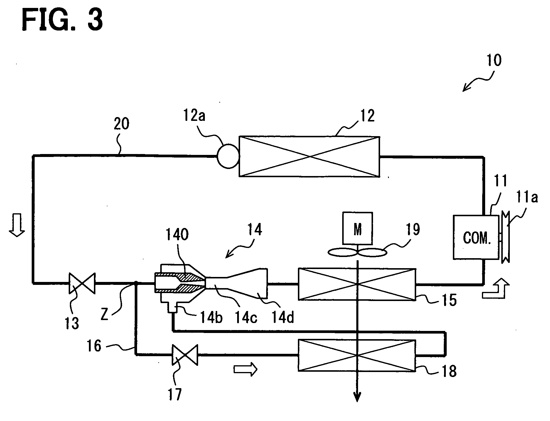
[0032]FIG. 1 shows an ejector 14 that is an example of an ejector device of a first embodiment of the present invention, FIG. 2 shows a nozzle 140 of the ejector 14, and FIG. 3 shows a refrigeration cycle apparatus 10 using the ejector 14.

[0033]The refrigeration cycle apparatus 10 shown in FIG. 3 can be used for a vehicle air conditioner, for example. As the refrigerant used in a refrigerant cycle of the refrigeration cycle apparatus 10, a refrigerant such as HFC134a may be used so that a refrigerant pressure on a high-pressure side does not excess the critical pressure of the refrigerant.

[0034]In the refrigeration cycle apparatus 10 shown in FIG. 3, a compressor 11 is configured to draw and compress the refrigerant and to discharge the compressed high-pressure and high-temperature refrigerant. The compressor 11 is driven and rotated by a vehicle engine (not shown) via an electromagnetic clutch 11a, a belt, or the like, as an example.

[0035]The compressor 11 may be a variable displac...

second embodiment

[0083]A second embodiment of the present invention will be described with reference to FIGS. 7 and 8. FIG. 7 is one example of a nozzle 140 according to the second embodiment, and FIG. 8 is another example of a nozzle 140 of the second embodiment. In FIGS. 7 and 8, parts having the same or corresponding functions in the nozzle 140 as those of the first embodiment are indicated by the same reference numbers.

[0084]In the example of the nozzle 140 of FIG. 7 in which the fluid passage 143 from the throat portion 144 to the jet port 142 is configured by a middle portion 148 and an outlet portion 148, the expanding angle θ1 of the passage wall surface of the middle portion 147 is constant in the whole area, and the expanding angle θ2 of the passage wall surface of the outlet portion 148 is also constant in the whole area while being larger than the expanding angle θ1 of the middle portion 147. That is, the expanding angle θ2 of the outlet portion 148 larger than the expanding angle θ1 of ...


PUM


Abstract

An ejector device includes a nozzle having an inner wall surface defining a circular cross-sectional fluid passage extending from an inlet to a jet port. Furthermore, the fluid passage has a throat portion at a position between the inlet and the jet port, and a passage expanding portion in which the cross-sectional area of the fluid passage is enlarged from the throat portion as toward downstream. The passage expanding portion includes a middle portion in which the inner wall surface is expanded in a fluid flow direction by a first expanding angle, and an outlet portion from a downstream end of the middle portion to the jet port, in which the inner wall surface is expanded in the fluid flow direction by a second expanding angle that is larger than the first expanding angle. The ejector device can be suitably used for a refrigeration cycle apparatus.

Description

CROSS REFERENCE TO RELATED APPLICATION[0001]This application is based on Japanese Patent Application No. 2008-064664 filed on Mar. 13, 2008, the contents of which are incorporated herein by reference in its entirety.FIELD OF THE INVENTION[0002]The present invention relates to an ejector device provided with a nozzle configured to jet a fluid, and a refrigeration cycle apparatus using the ejector device.BACKGROUND OF THE INVENTION[0003]Conventionally, an ejector device for a refrigerant cycle is described in JP 11-37577A. In the ejector device, upstream and downstream throttle portions are provided in a nozzle body at an upstream side of a jet port of the nozzle body, and a fluid passage is expanded from the downstream throttle portion as a throat portion toward the jet port so that refrigerant is decompressed in the fluid passage and the pressure energy of the refrigerant is converted to the speed energy of the refrigerant. In order to improve nozzle efficiency by converting the pre...

Claims


Application Information

Patent Timeline
Patent Type & Authority Applications(United States)
IPC IPC(8): F25B1/06B05B1/34
CPCF25B5/04F25B2500/01F25B2341/0012F25B41/00B60H2001/3298
Inventor OGATA, GOUTANISHIJIMA, HARUYUKIYAMADA, ETSUHISAGOCHO, MIKAMATSUI, HIDEYAKAYANO, KENTAHANO, TERUYUKI
Owner DENSO CORP
Learn More