Planter with direct hydraulic seed drive

Inactive Publication Date: 2009-09-17
BLUE LEAF I P
View PDF5 Cites 26 Cited by
  • Summary
  • Abstract
  • Description
  • Claims
  • Application Information

AI Technical Summary

Problems solved by technology

Sprocket and chain mechanisms require tedious adjustments and maintenance by the operator, including frequent lubrication.
A loose chain will result in inefficient drive mot

Method used


Image

  • Planter with direct hydraulic seed drive
  • Planter with direct hydraulic seed drive
  • Planter with direct hydraulic seed drive

Examples


Example

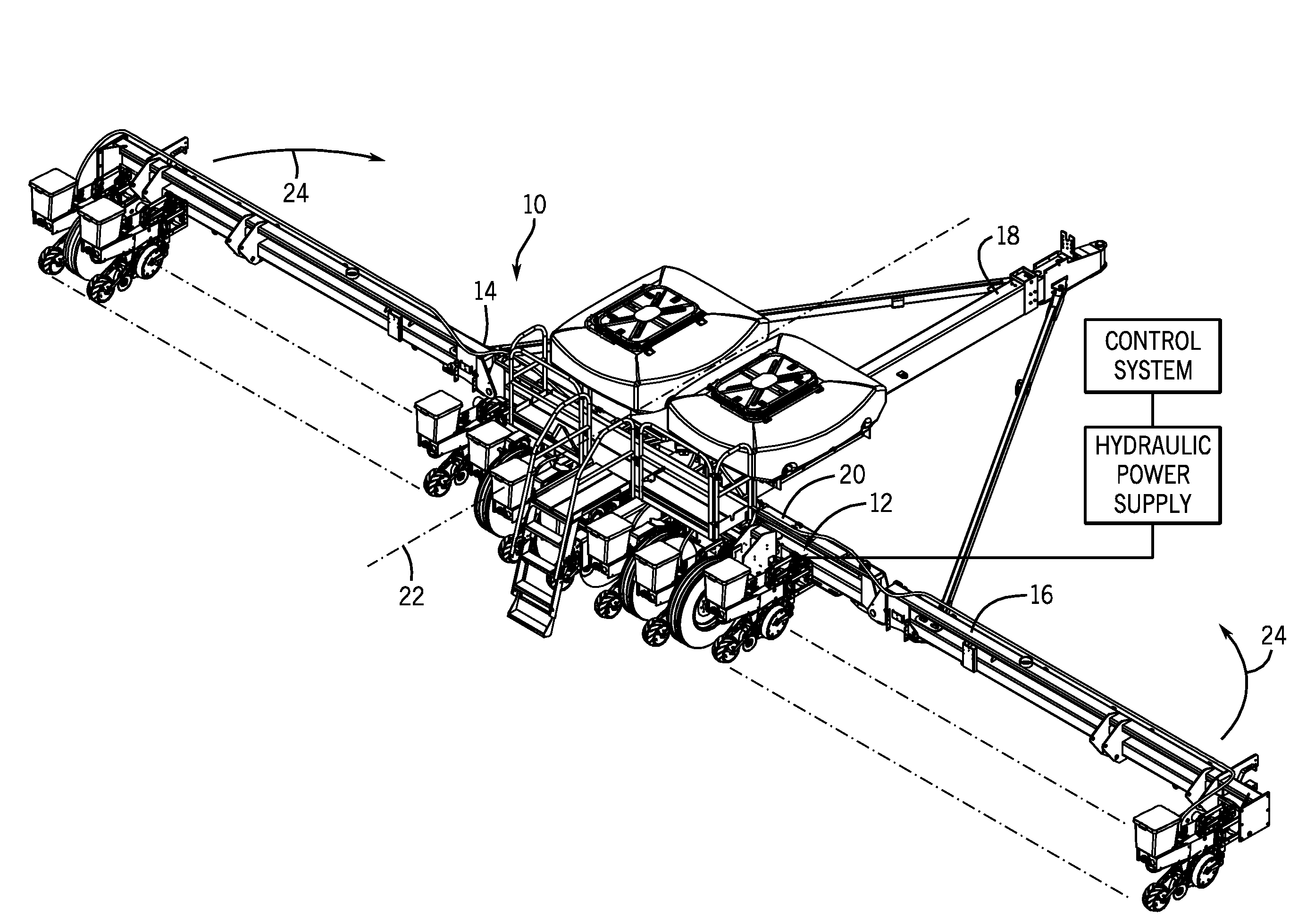
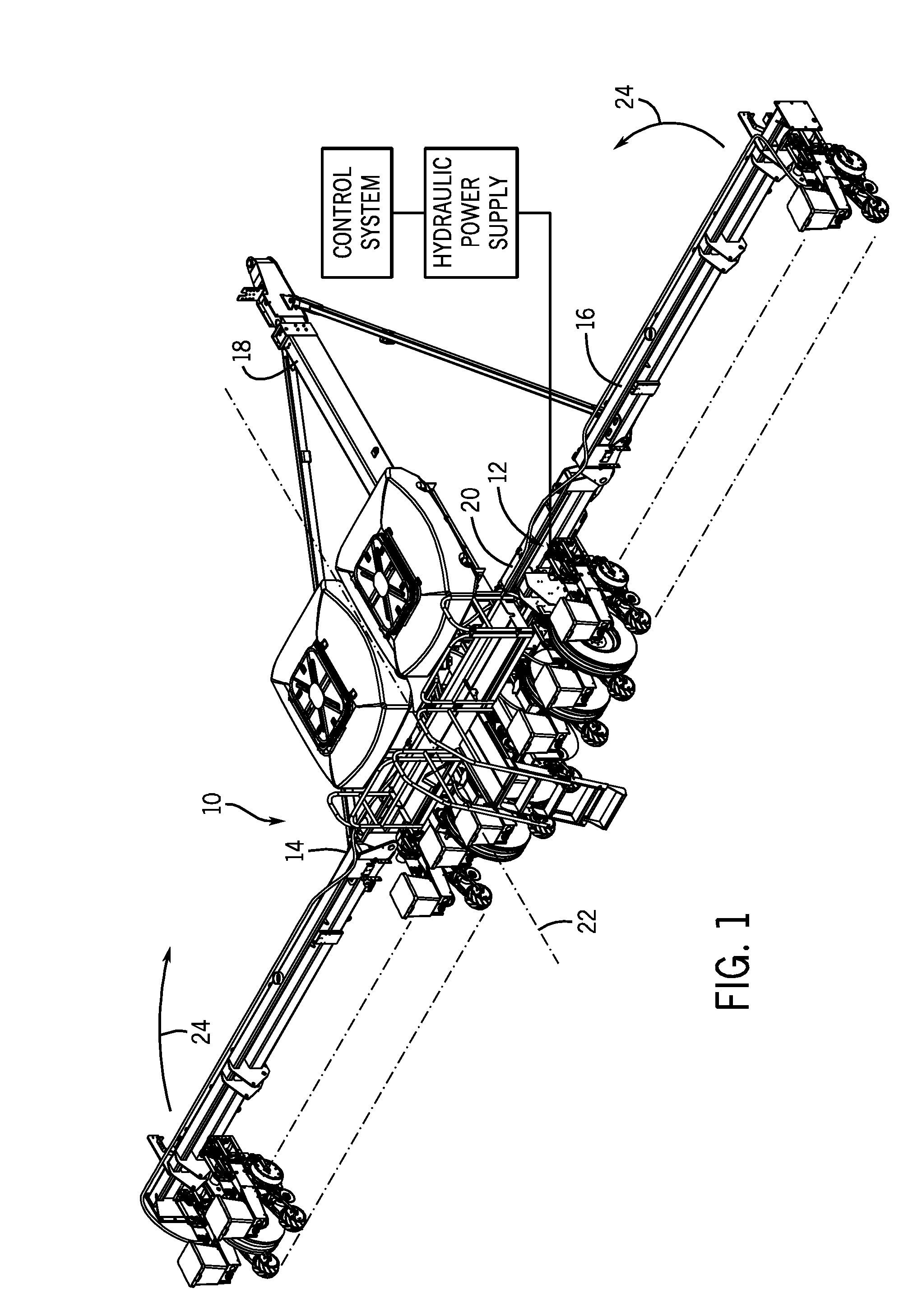
[0012]Turning now to the drawings, and referring first to FIG. 1, a planter 10 is shown, having a seed drive system 12. The planter is designed to be towed behind a work vehicle, such as tractor (not shown). As will be appreciated by those skilled in the art, the seed drive system is coupled to a power supply and a control system, represented as a block diagram for the sake of simplicity. The power supply and control system are used to regulate the seed drive system to attain desired seed spacing as well as to account for overall speed of the implement. The power supply will generally include a hydraulic power supply (not separately shown) that provides a flow of pressurized hydraulic fluid for driving parts of the seed drive system, as described below. The hydraulic power supply itself may be driven by a motor (not shown) or by the tractor itself (e.g., by a power takeoff shaft), or may be part of the tractor hydraulic system.

[0013]The planter 10 consists of a frame, designated gen...


PUM


Abstract

The invention provides an innovative yet straightforward approach to driving the seed distribution system in planters which feature hinged winged extensions. The flexibility of the hinged winged extensions may allow the planter to adjust to the contours of a field and to fold to facilitate transport of the planter. In one embodiment, for example, the invention may provide a mechanical coupling between several sections of a seed drive shaft which may support and be driven by a hydraulic motor for each of the winged sections. The seed drive system may also be coupled to row units to synchronize and power the distribution of seeds by the planter.

Description

BACKGROUND[0001]The present invention relates generally to agricultural implements, and more particularly to a planter or similar implement designed to be towed behind a work vehicle, and that is equipped with a seed distribution system.[0002]A wide range of agricultural implements are known and are presently in use, particularly designed for towing behind a work vehicle, such as a tractor. In one family of such implements, including tillers, planters, and so forth, a wide swath of ground can be tilled, planted, or otherwise worked in each pass of the implement in a tilled or untilled field. Planters, for example, often include frames supported by series of wheels and a tool bar extending transversely with respect to a line of movement of the implement across the field. Seed tanks are typically supported on the implement support structure, such as just forward of or over the tool bar. Large amounts of seed may be poured into these tanks and, as the implement is advanced across the f...

Claims


Application Information

Patent Timeline
IPC IPC(8): A01C7/18
CPCA01C7/208A01B73/065Y10S111/921
Inventor JAIME, RICHARD J.CONNORS, MICHAELBETTIN, LEONARD A.HORN, RODNEY SAMUEL
Owner BLUE LEAF I P
Why Eureka
Try Eureka