Vehicle fairing structure

a technology for fairings and vehicles, applied in vehicle arrangements, roofs, transportation and packaging, etc., can solve the problems of increasing fuel consumption, increasing emissions of greenhouse gasses and other pollutants, increasing the cost of operation, and increasing the amount of power needed to move a vehicle over land or through the air. , to achieve the effect of reducing gap drag, reducing fuel consumption, and eliminating gap drag

Active Publication Date: 2009-09-17
ZF COMPOSITES NORTH AMERICA LTD
View PDF59 Cites 56 Cited by
  • Summary
  • Abstract
  • Description
  • Claims
  • Application Information

AI Technical Summary

Benefits of technology

[0011]By virtue of the foregoing design, the current invention is a device which traps air and creates an over-pressure area. Such over-pressure area acts to impede wind and airflow created by a moving Truck from penetrating the Gap, hence Gap related dr...

Problems solved by technology

The amount of power needed to move a vehicle over land or through the air increases with the speed of the vehicle due to aerodynamic drag.
The amount of power necessary to overcome aerodynamic drag directly translates into increased fuel consumption, and thus cost of operation and increased emission of greenhouse gasses and other pollutants.
While this fairing structure significantly reduces drag at the rear end of the trailer box, a significant amount of drag is also associated with the front of the trailer box, and in particular in the gap between the T...

Method used


Image

  • Vehicle fairing structure
  • Vehicle fairing structure
  • Vehicle fairing structure

Examples


Embodiment Construction

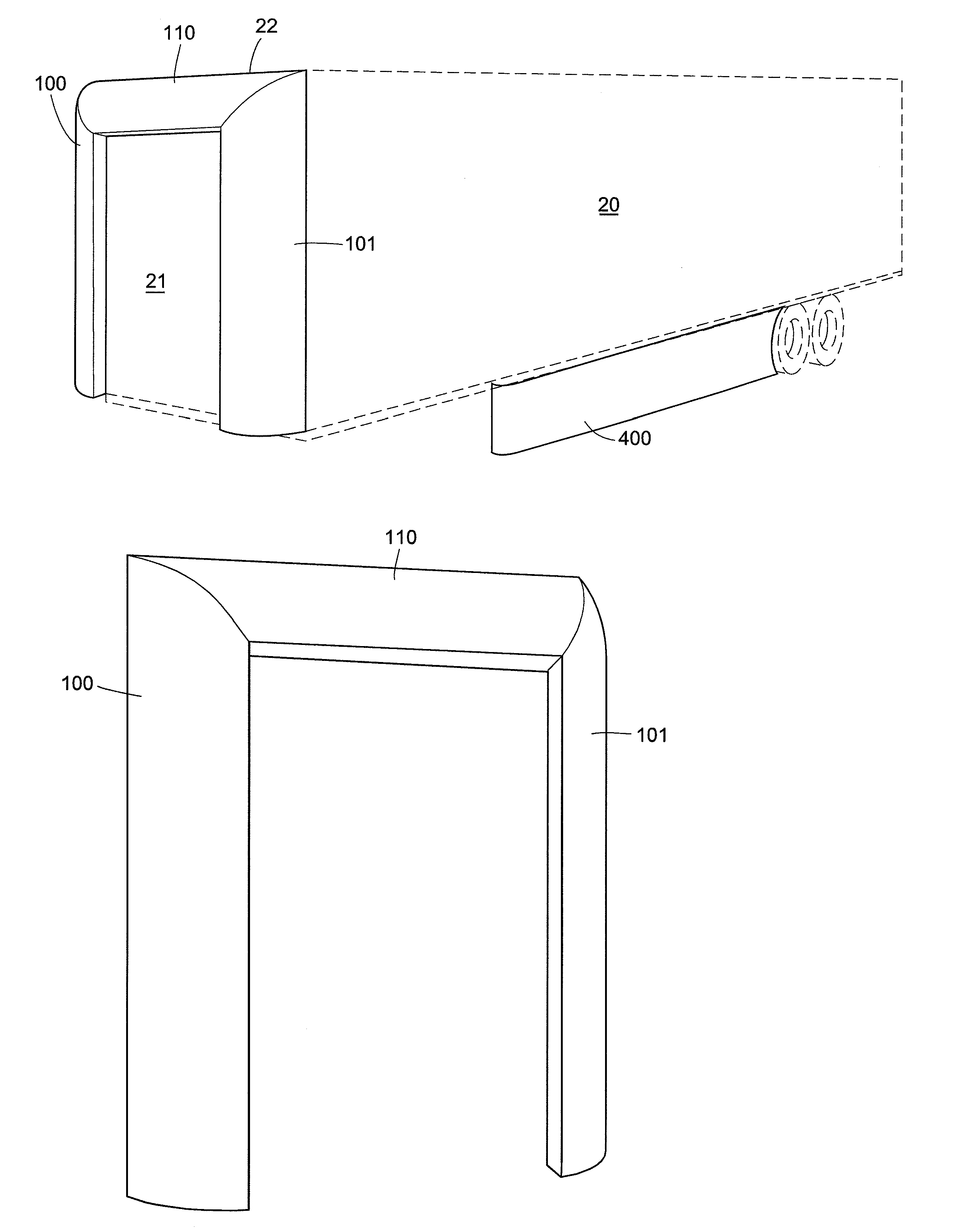
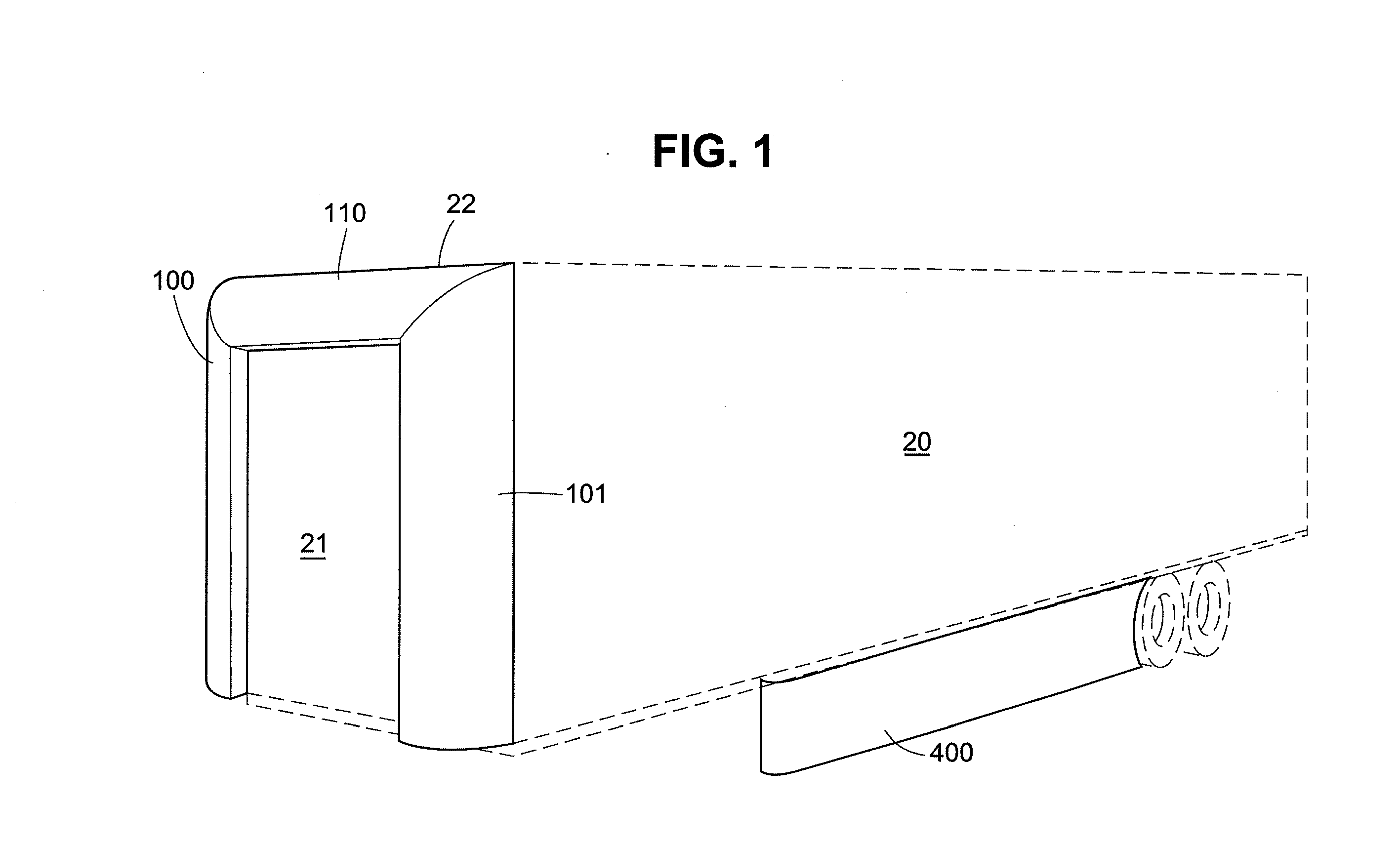
[0022]The preferred embodiment of the instant invention is a three sided airfoil that “traps” air within the Gap and creates a pressure bubble within the Gap that effectively fills the Gap, thereby reducing or eliminating aerodynamic drag caused by A) wind entering the Gap and striking the front flat surface of the trailer box 21 and B) vortices created by (i) differences in air pressure between the sides and top of the Truck's tractor and trailer, (ii) the space comprising the Gap, (iii) differences in air flow along the sides and top of the Truck's tractor and trailer, and (iv) differences in air flow in and around the space comprising the Gap.

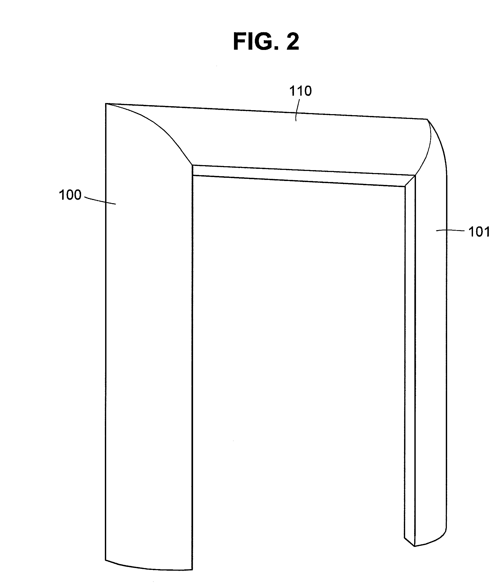
[0023]FIGS. 1 and 2 depict a preferred embodiment of the present invention, comprising a three sided airfoil adjacent to, concurrent with, and forming a continuation of the sides and top of the box of Trailer 20.

[0024]With reference to FIG. 1, there is shown fairing side 100, which comprises one of the sides of the fairing in the preferred e...


PUM


Abstract

A fairing structure for a vehicle having a front vehicular component and a rear vehicular component in tandem and separated by a gap, comprising a top fairing surface adapted to be attached to the rear vehicular component, a first side surface adapted to be attached to a first side of the rear vehicular component, joining a first end of the top surface and generally perpendicular to the top surface, and a second side surface adapted to be attached to a second side of the rear vehicular component, joining a second end of the top surface opposite the first end and generally perpendicular to the top surface. Each of the top and first and second side surfaces has a proximal edge adapted to be positioned adjacent a vehicle, as well as a distal edge adapted to be positioned away from the vehicle with respect to the respective proximal edge. The proximal edges of the top and side surfaces attach to the leading top and side edges, respectively, of the front surface of the trailer box, so that an approximately uninterrupted surface is formed from the fairing structure to top and sides of the rear vehicular component. The area bounded by the distal edges of the surfaces is smaller than an area bounded by the proximal edges. The top side surface, the first side surface and the second side surface are made of a resilient material in the regions distal from the regions where the first side surface joins the top side surface, and where the second side surface joins the top side surface, the top side surface including a heat and fire resistant material in the regions proximate to the first and second side surface, and the first and second side surfaces including a heat and fire resistant material in the regions proximate to the top side surface.

Description

[0001]This application claims the benefit of U.S. patent application Ser. No. 11 / 684,097, filed Mar. 9, 2007, the contents of which are incorporated by reference as if fully set forth herein.BACKGROUND OF THE INVENTION[0002]This invention relates to structures for improving the aerodynamic profile of vehicles, especially for the front end of a trailer box in a tractor-trailer combination.DESCRIPTION OF RELATED ART[0003]The amount of power needed to move a vehicle over land or through the air increases with the speed of the vehicle due to aerodynamic drag. The amount of power necessary to overcome aerodynamic drag directly translates into increased fuel consumption, and thus cost of operation and increased emission of greenhouse gasses and other pollutants.[0004]A variety of innovations aimed at reducing the aerodynamic drag of various transport vehicles, including tractor-trailer combinations (“Truck(s)”), have been introduced in the prior art. These include efforts to make the hood...

Claims


Application Information

Patent Timeline
IPC IPC(8): B62D35/00
CPCB62D35/001
Inventor REIMAN, JAMESHEPPEL, PETER
Owner ZF COMPOSITES NORTH AMERICA LTD
Why Eureka
Try Eureka