Stator mounting method

a mounting method and stator technology, applied in the direction of magnets, windings, magnetic bodies, etc., can solve the problems of difficult to absorb dispersion, limit the enhancement of accuracy, and inferiority in automatic assembly properties, so as to reduce the number of rejects, improve the mounting properties, and reduce the dispersion of the mounting position

Inactive Publication Date: 2009-09-17
TOYOTA JIDOSHA KK
View PDF3 Cites 15 Cited by
  • Summary
  • Abstract
  • Description
  • Claims
  • Application Information

AI Technical Summary

Benefits of technology

[0013]If the height from the inner peripheral face of the frame body to the lead wire pullout portion is set equal to the distance from the upper face of the frame body insertion portion of the stator core to the lead wire insertion position inner peripheral lower face of the terminal portion, the height of the lead wire is made substantially equal to the height of the terminal portion by holding the upper face of the frame body insertion portion of the stator core in contact with the upper side of the inner peripheral face of the frame body after the lead wire is inserted into the terminal portion following the start of insertion of the frame body into the stator core. As a result, the dispersion of a mounting position is reduced. When the concentrated winding coil unit is mounted on the stator core according to the related art, no consideration is given to the mounting of the lead wire on the terminal portion as described above. Therefore, an improvement in mounting properties and a reduction in the number of rejects can be expected by adopting a construction in which the heights of the lead wire and the terminal portion are constant as described above. Accordingly, it is possible to provide a stator mounting method capable of absorbing the dispersion of a lead wire of a concentrated winding coil unit to make an improvement in automatic mounting properties.
[0014]According to the foregoing aspect of the invention, the frame body can be reliably pressed against the upper face of the frame body insertion portion of the stator core by the pressurization means, and the lead wire can be accurately mounted on the terminal portion. The operation of inserting the frame body into the stator core is under many restrictions, and structurally has almost no room for the use of a guide jig or the like. However, a reduction in dispersion can be expected simply by pressing the frame body or the coil unit against the stator core with the aid of the pressurization means. Therefore, this method is adoptable even at a location under many restrictions in terms of space.

Problems solved by technology

In the case where the concentrated winding coil units as described above are mounted on the stator to manufacture the motor, there is a problem of the inferiority in automatic assembly properties.
However, due to a construction in which a lead wire is pulled out from the coil unit, there is a limit to the enhancement of the accuracy.
However, the art disclosed in Japanese Patent Application Publication No. 2007-215356 (JP-A-2007-215356) is considered to have the following problem.
It is difficult to absorb this dispersion with the aforementioned construction.
This reduction in the size of the motor leads to a deterioration in the assembly properties in assembling the coil unit with the stator core, and constitutes a limiting factor for automation.
In particular, the mounting of the lead wire protruding from the coil unit on the end terminal is likely to cause dispersion and hence gives rise to a problem.
However, since there is only a small room in the vertical direction, it is difficult to ensure a clearance for absorbing dispersion through the method disclosed in Japanese Patent Application Publication No. 2007-215356 (JP-A-2007-215356).

Method used


Image

  • Stator mounting method
  • Stator mounting method
  • Stator mounting method

Examples


Embodiment Construction

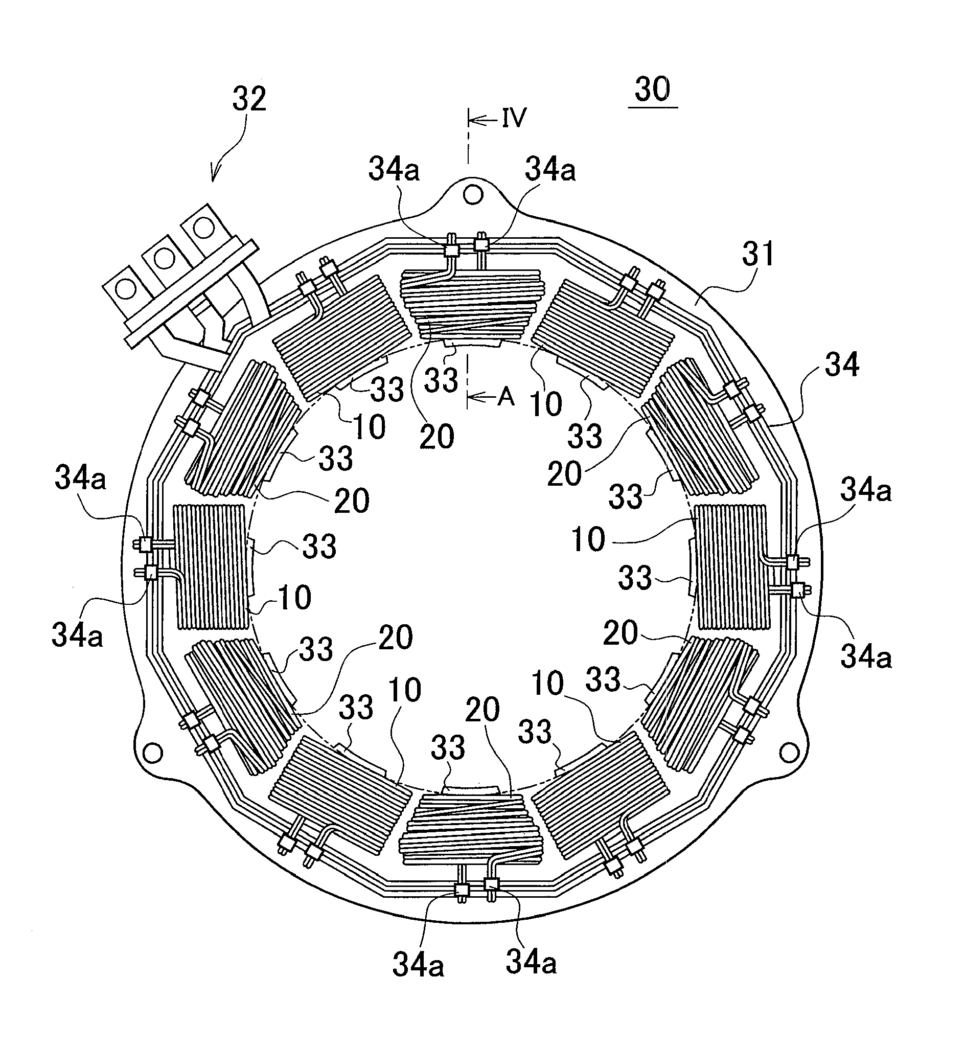
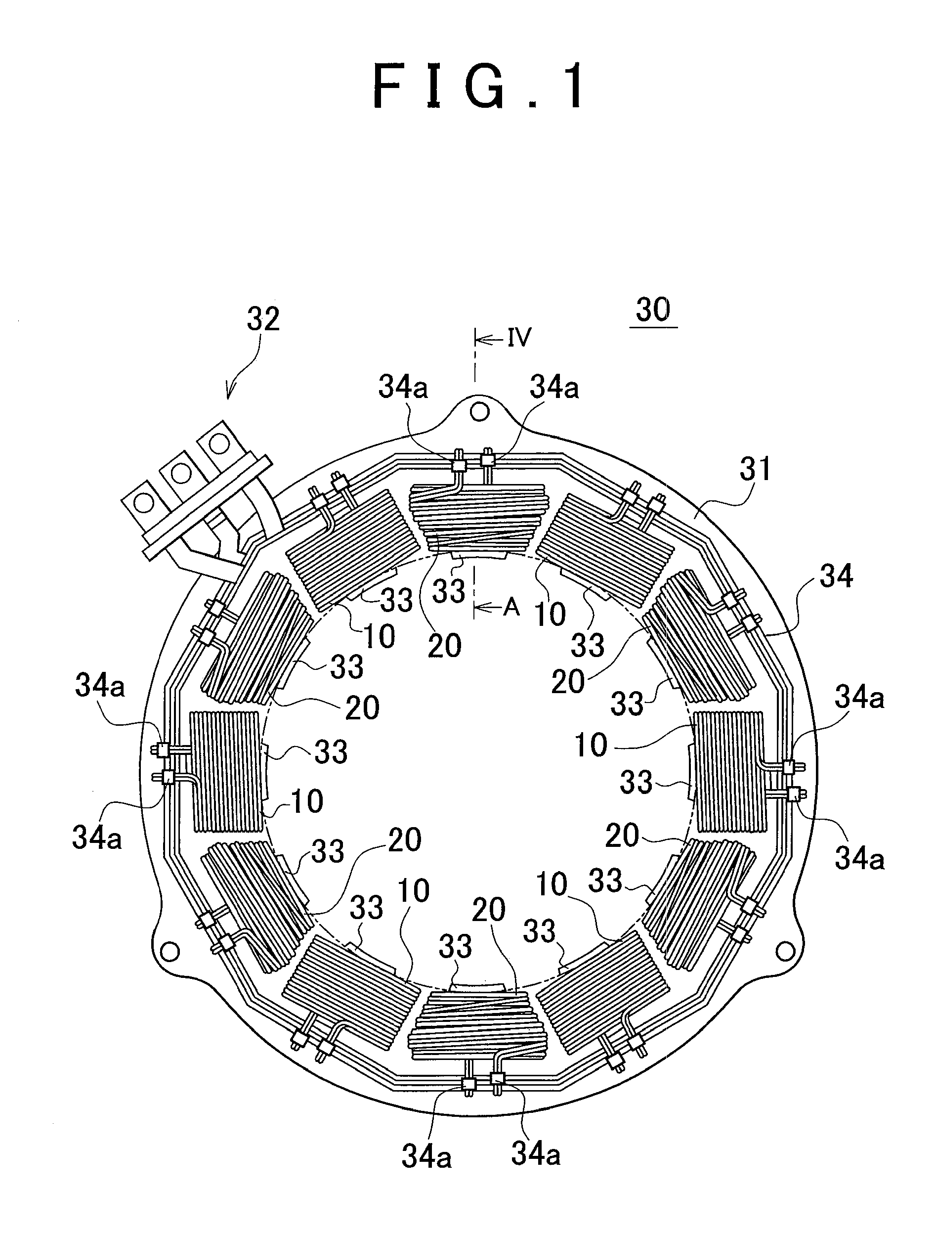
[0027]A stator mounting method according to the invention will be described with reference to the drawings. FIG. 1 is a top view of the stator according to this embodiment of the invention. A stator 30 is manufactured by alternately inserting rectangular coil units 10 and tapered coil units 20 into a stator core 31 formed of laminated steel plates. The rectangular coil units 10 and the tapered coil units 20 are concentrated winding coil units. The stator core 31 is formed by cylindrically laminating the laminated steel plates, and is provided on an inner peripheral side thereof with a plurality of convex teeth portions 33. The rectangular coil units 10 and the tapered coil units 20 are alternately inserted into these teeth portions 33.

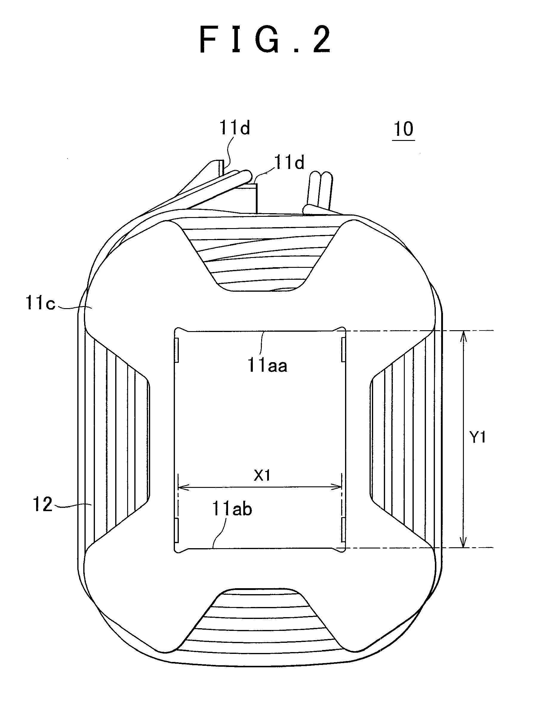
[0028]FIG. 2 is a plan view of each of the rectangular coil units 10 as viewed from an inner periphery side of the stator core 31 when mounted on the stator core 31. FIG. 3 is a plan view of each of the rectangular coil units 10 as viewed from an outer...


PUM

PropertyMeasurementUnit
distanceaaaaaaaaaa
heightaaaaaaaaaa
dispersionaaaaaaaaaa

Abstract

In a stator mounting method in which a coil unit is inserted into a stator core and a lead wire protruding from the coil unit is inserted into and mounted on a terminal portion of the stator core, the lead wire is passed through a lead wire pullout portion located at a predetermined position of a coil frame body, a height from an inner peripheral upper face of the coil frame body to the lead wire pullout portion is equalized with a distance from a core upper face of the stator core to a lead wire insertion position inner peripheral lower face of the terminal portion, and the core upper face of the stator core is held in contact with an inner peripheral upper face of the coil frame body after the lead wire is inserted into the terminal portion.

Description

INCORPORATION BY REFERENCE[0001]The disclosure of Japanese Patent Application No. 2008-062362 filed on May 12, 2008 including the specification, drawings and abstract is incorporated herein by reference in its entirety.BACKGROUND OF THE INVENTION[0002]1. Field of the Invention[0003]The invention relates to an art of mounting a concentrated winding coil unit on a stator of a motor, and to an art of making an improvement in automatic assembly properties.[0004]2. Description of the Related Art[0005]In recent years, as is the case with hybrid vehicles, the number of cases in which a large motor used for driving is mounted on a vehicle has been increasing. In a stator employed in such an on-vehicle motor, a plurality of concentrated winding coil units, with coils wound therearound, are fitted on a stator core. Coil terminals provided on the concentrated winding coil units are inserted into end terminals on a wire connection terminal side provided on the stator, and are connected thereto ...

Claims


Application Information

Patent Timeline
Patent Type & Authority Applications(United States)
IPC IPC(8): H02K11/00
CPCH02K3/522Y10T29/49071Y10T29/49073
Inventor HIRAO, YASUYUKI
Owner TOYOTA JIDOSHA KK
Why Eureka
Try Eureka