
Ocular light stimulus apparatus

Inactive Publication Date: 2009-09-17
KOWA CO LTD
View PDF0 Cites 3 Cited by
  • Summary
  • Abstract
  • Description
  • Claims
  • Application Information

AI Technical Summary

Benefits of technology

[0013]In the invention, the position of the stimulus light source and the size of the stimulus light can be varied, so that a bioelectrical signal can be obtained from the various areas of the retina of the eye under examination, thus assuring a reliable local biological examination.
[0015]In the invention, it is possible to fix the operating member that is operated so as to move the stimulus light source, so that the movement of the projected stimulus light can be locked. This allows the burden on the examiner to be alleviated and a reliable local ERG examination to be performed.

Problems solved by technology

In the conventional techniques, the position of the stimulus light source or the size of the stimulus light is not varied when the local ERG examination is performed, and as a result, drawbacks occur in that a bioelectric signal is not obtained from an arbitrary position of the retina, and a reliable local ERG examination is difficult to perform.
When the stimulus light projection position is varied in the local ERG examination, drawbacks also occur in that the projection position is not easily maintained at a prescribed position, and a reliable bioelectric signal is difficult to obtain from the retina.

Method used


Image

  • Ocular light stimulus apparatus
  • Ocular light stimulus apparatus
  • Ocular light stimulus apparatus

Examples


Embodiment Construction

[0029]The present invention will now be described in detail with reference to the embodiments shown in the attached drawings.

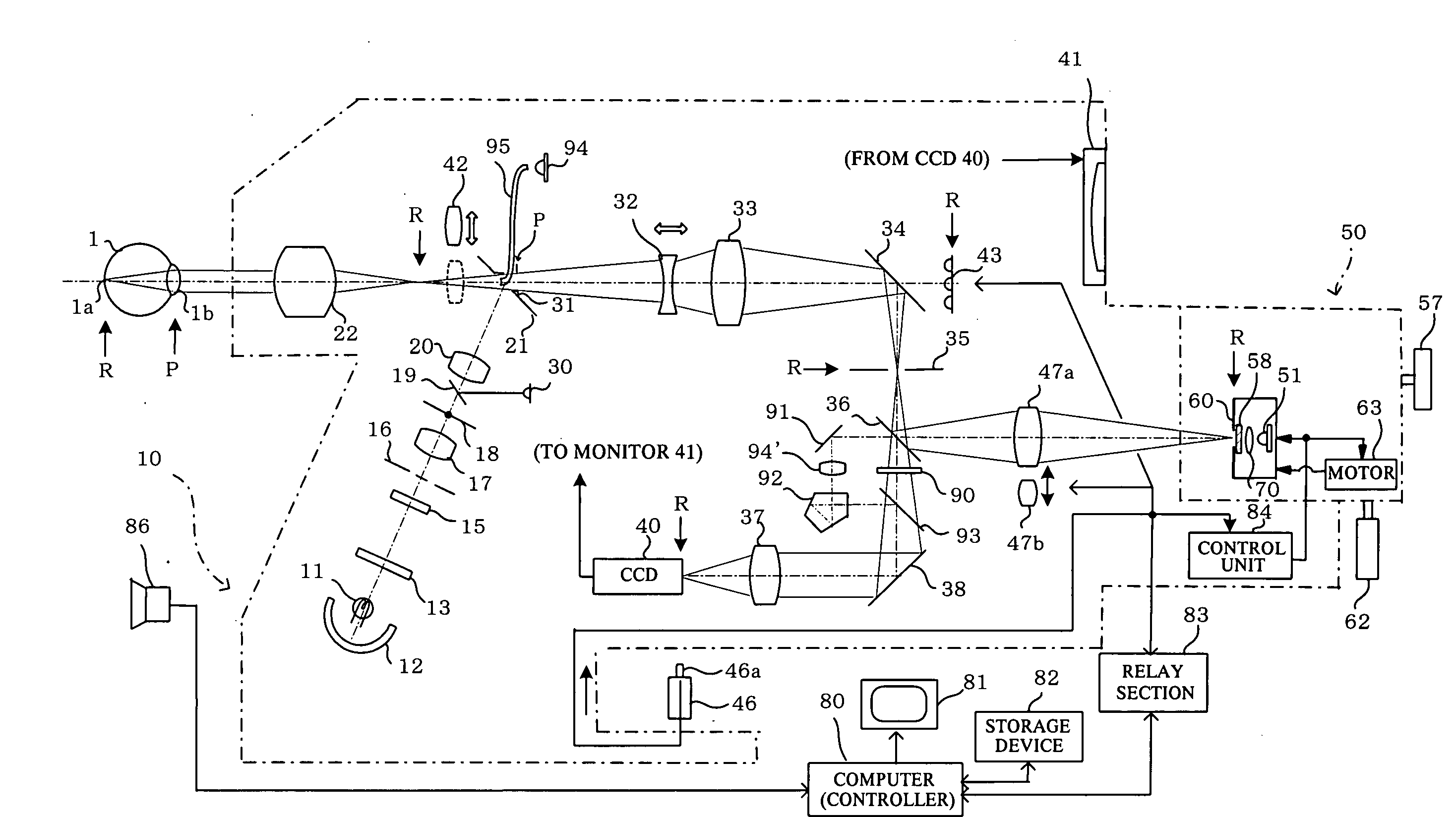
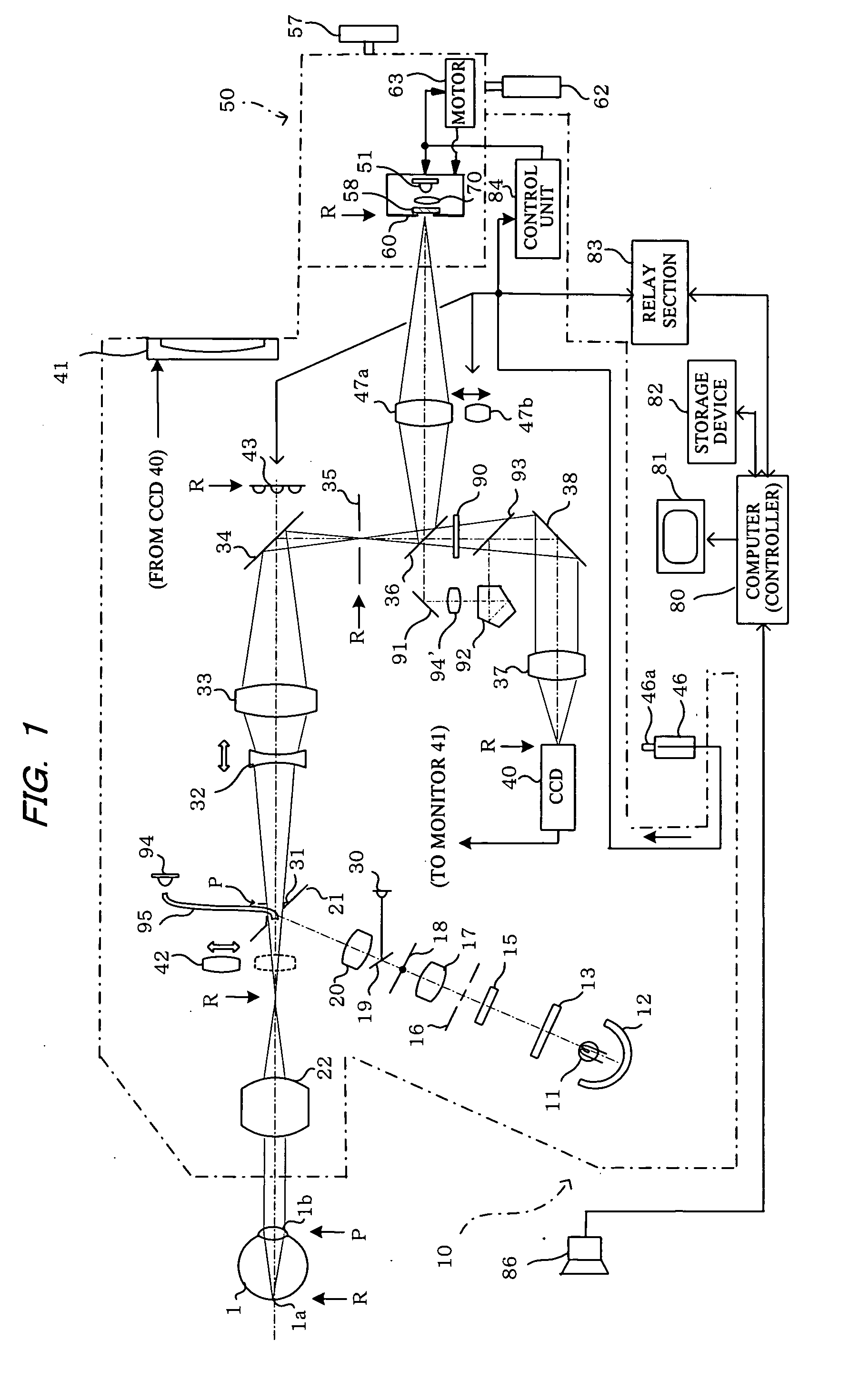
[0030]FIG. 1 shows an ocular light stimulus apparatus that comprises a light stimulus unit 10 and a stimulus light source unit 50. In FIG. 1, the reference symbol R indicates the position conjugate with a fundus 1a of an eye 1 under examination, and the reference symbol P indicates the position conjugate with the anterior ocular segment 1b (particularly the pupil) thereof.

[0031]The light stimulus unit 10 is provided with an illumination optical system for illuminating the fundus of the eye under examination, and an imaging optical system for imaging the illuminated fundus. In the illumination optical system, light emitted from a halogen lamp or other illumination light source 11, and light reflected by a concave mirror 12 are converted to infrared light via a visible-cutting infrared-transmitting filter 13 and directed into a diffusing plate 15 that diffuses t...


PUM


Abstract

A stimulus light from a stimulus light source is projected to the retina of an ocular fundus under examination to stimulate the retina in localized fashion to generate a bioelectric signal from the retina. The stimulus light source is mounted on a movable block, and an operating lever is used to move the stimulus light source to change the stimulus light on the retina. The size of the stimulus light can also be varied using a panel having a plurality of openings with different diameters for allowing the stimulus light to pass through. This assures a reliable local ERG examination because the bioelectrical signal can be produced in a wider area of the retina. The operating lever is further fixed by inserting a cap to keep the projected stimulus light unchanged. This allows the burden on the examiner to be reduced remarkably, assuring a reliable local ERG examination.

Description

BACKGROUND OF THE INVENTION[0001]1. Field of the Invention[0002]The present invention relates to an ocular light stimulus apparatus, and more particularly relates to an ocular light stimulus apparatus for providing localized light stimulus to a retina of an ocular fundus under examination by stimulus light from a stimulus light source to perform biological examination through use of a bioelectrical signal from the retina.[0003]2. Description of the Prior Art[0004]Conventional known methods used primarily for ophthalmic examination include not only capturing a fundus image and performing fundus examination, but also electroretinogram (ERG) examination in which stimulus light is radiated to a retina, an action potential generated in the retina is measured, and an electroretinogram is created to perform an ophthalmic biological examination.[0005]In an ERG examination, a background light is needed for illuminating the background onto which the stimulus light is radiated, and the quality...

Claims


Application Information

Patent Timeline
IPC IPC(8): A61B3/14
CPCA61B5/0496A61B5/398
Inventor HARA, TAKUYAMATSUMURA, KAZUNORIFUJII, TATSUYAMIZUOCHI, MASAHARU
Owner KOWA CO LTD
Learn More