
Micro-Annulus Detection Using Lamb Waves

a technology of micro-annulus and lamb waves, which is applied in the field of micro-annulus detection using lamb waves, can solve the problems of increasing production costs, affecting reducing the detection accuracy of micro-annulus,

Inactive Publication Date: 2009-09-17
BAKER HUGHES INC
View PDF13 Cites 27 Cited by
  • Summary
  • Abstract
  • Description
  • Claims
  • Application Information

AI Technical Summary

Problems solved by technology

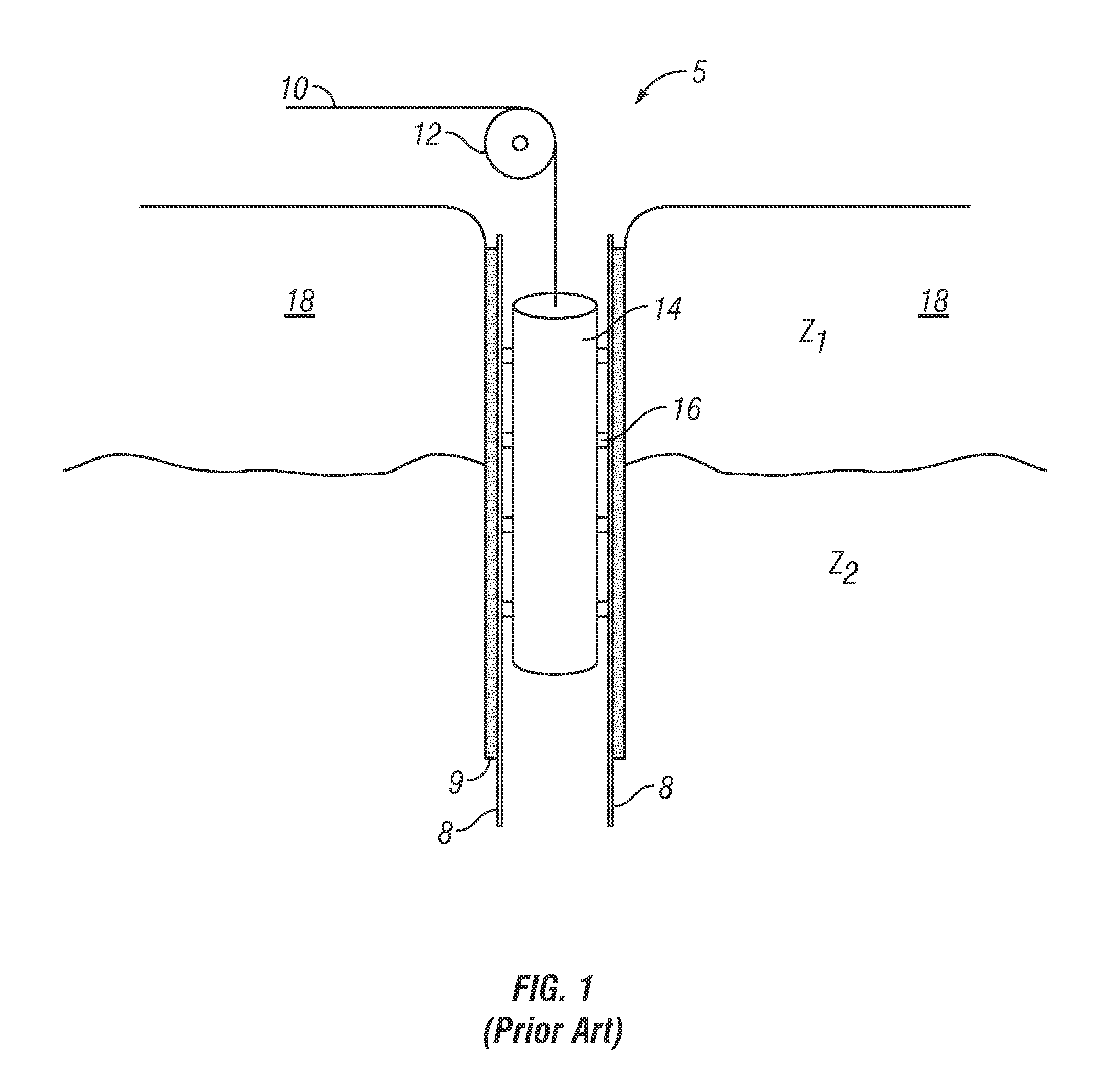
Should the cement 9 surrounding the casing 8 be defective and fail to provide isolation of the adjacent zones, water or other undesirable fluid can migrate into the hydrocarbon producing zone thus diluting or contaminating the hydrocarbons within the producing zone, and increasing production costs, delaying production or inhibiting resource recovery.
Prior art methods have not addressed the problem of identification of a micro-annulus.

Method used


Image

  • Micro-Annulus Detection Using Lamb Waves
  • Micro-Annulus Detection Using Lamb Waves
  • Micro-Annulus Detection Using Lamb Waves

Examples


Embodiment Construction

[0023]Changes in ultrasonic wave propagation speed, along with energy losses from interactions with materials microstructures are often used to nondestructively gain information about properties of the material. An ultrasonic wave, such as a Lamb wave or a shear horizontal (SH) wave, may be created in a material sample, such as a solid beam, by creating an impulse at one region of the sample. As the wave propagates through the casing, the casing state with respect to the formation affects the wave. Once the affected wave is recorded, the casing state can be determined.

[0024]The amount of attenuation can depend on how an acoustic wave is polarized and the coupling condition between the casing and the cement. Typical downhole tools having acoustic wave transducers generate acoustic waves that are polarized perpendicular to the surface of the casing. The attenuation of the acoustic wave as it propagates along the surface of the casing depends on the condition of the cement bond and is ...


PUM


Abstract

A method, apparatus and computer-readable medium for identifying a micro-annulus outside a casing in a cemented wellbore. The attenuation of a Lamb wave and a compressional wave is used to determine a presence of a micro-annulus between the casing and the cement.

Description

BACKGROUND OF THE DISCLOSURE[0001]1. Field of the Disclosure[0002]The disclosure relates generally to determining an integrity of cement between a casing in a wellbore in a formation and the surrounding formation. More specifically, the present disclosure relates to a method of detecting the presence of micro-annular gaps using Lamb waves within a wellbore casing.[0003]2. Description of Related Art[0004]As illustrated in FIG. 1 wellbores typically include casing 8 set within the wellbore 5, where the casing 8 is bonded to the wellbore by adding cement 9 within the annulus formed between the outer diameter of the casing 8 and the inner diameter of the wellbore 5. The cement bond not only adheres to the casing 8 within the wellbore 5, but also serves to isolate adjacent zones (e.g. Z1 and Z2) within an earth formation 18. Isolating adjacent zones can be important when one of the zones contains oil or gas and the other zone includes a non-hydrocarbon fluid such as water. Should the cem...

Claims


Application Information

Patent Timeline
IPC IPC(8): G01V1/40
CPCG01V1/50G01N29/04G01N29/06G01N29/11
Inventor BOLSHAKOV, ALEXEIDOMANGUE, EDWARD J.PATTERSON, DOUGLAS J.
Owner BAKER HUGHES INC
Learn More