Registration of 3D point cloud data by creation of filtered density images

Inactive Publication Date: 2009-09-17
HARRIS CORP
View PDF56 Cites 73 Cited by
  • Summary
  • Abstract
  • Description
  • Claims
  • Application Information

AI Technical Summary

Benefits of technology

[0016]The global transform that is used with the present invention advantageously collects all the correspondences for each pair of frames of interest. In this regard it should be understood that the term “pairs” as used herein does not refer merely to frames that are adjacent such as frame 1 and frame 2. Instea

Problems solved by technology

One problem that frequently arises with imaging systems is that targets may be partially obscured by other objects which prevent the sensor from properly illuminating and imaging the target.
For example, in the case of an optical type imaging system, targets can be occluded by foliage or camouflage netting, th

Method used


Image

  • Registration of 3D point cloud data by creation of filtered density images
  • Registration of 3D point cloud data by creation of filtered density images
  • Registration of 3D point cloud data by creation of filtered density images

Examples


Embodiment Construction

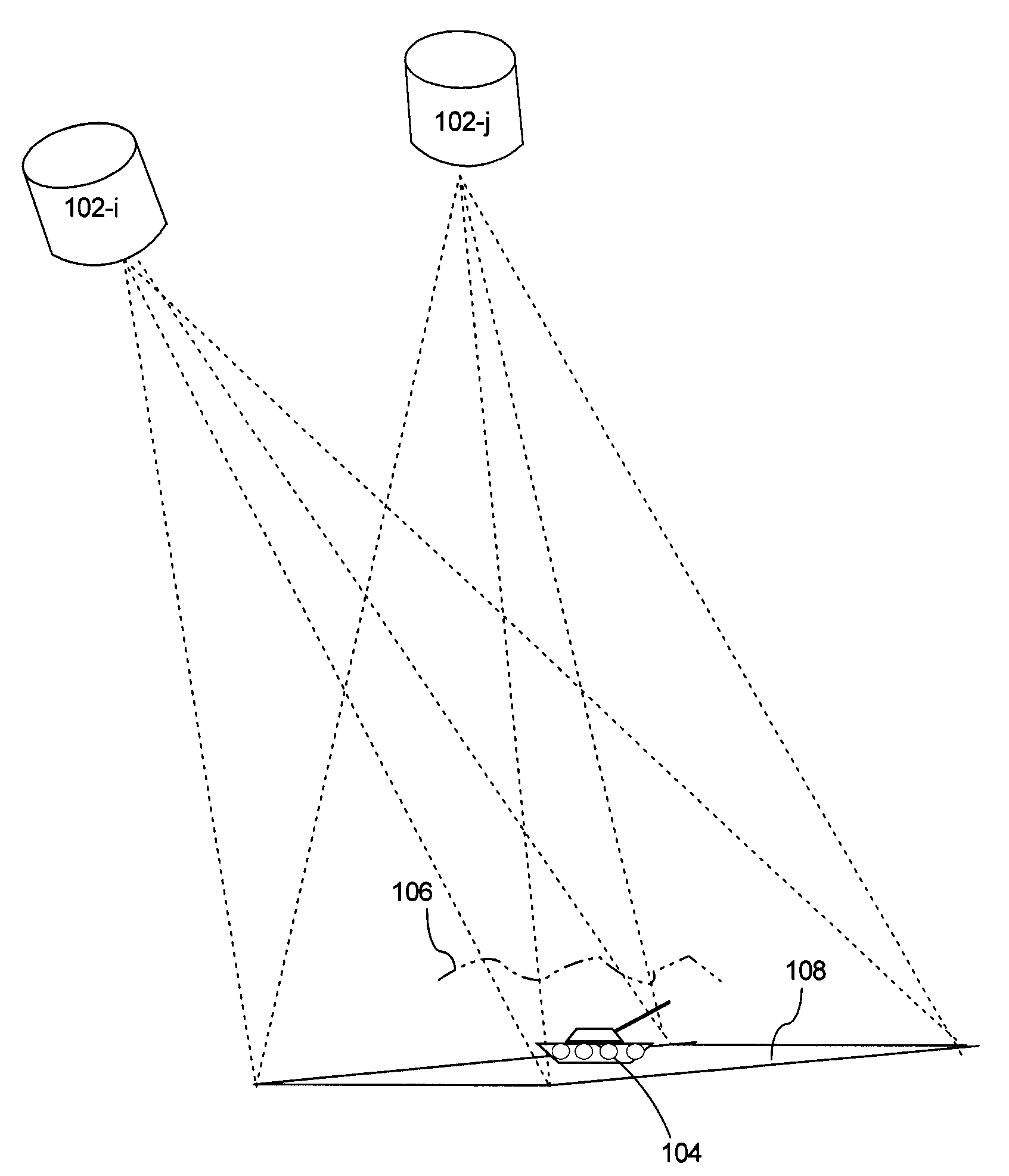
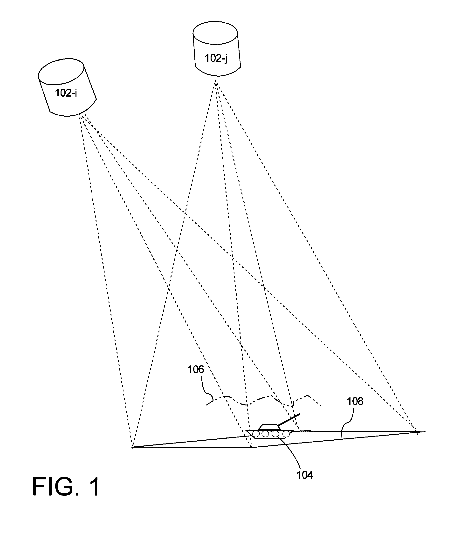
[0030]In order to understand the inventive arrangements for registration of a plurality of frames of three dimensional point cloud data, it is useful to first consider the nature of such data and the manner in which it is conventionally obtained. FIG. 1 shows sensors 102-i, 102-j at two different locations at some distance above a physical location 108. Sensors 102-i, 102-j can be physically different sensors of the same type, or they can represent the same sensor at two different times. Sensors 102-i, 102-j will each obtain at least one frame of three-dimensional (3D) point cloud data representative of the physical area 108. In general, the term point cloud data refers to digitized data defining an object in three dimensions.

[0031]For convenience in describing the present invention, the physical location 108 will be described as a geographic location on the surface of the earth. However, it will be appreciated by those skilled in the art that the inventive arrangements described he...


PUM


Abstract

Method (300) for registration of two or more of frames of three dimensional (3D) point cloud data (200-i, 200-j). A density image for each of the first frame (frame i) and the second frame (frame j) is used to obtain the translation between the images and thus image-to-image point correspondence. Correspondence for each adjacent frame is determined using correlation of the ‘filtered density’ images. The translation vector or vectors are used to perform a coarse registration of the 3D point cloud data in one or more of the XY plane and the Z direction. The method also includes a fine registration process applied to the 3D point cloud data (200-i, 200-j). Corresponding transformations between frames (not just adjacent frames) are accumulated and used in a ‘global’ optimization routine that seeks to find the best translation, rotation, and scale parameters that satisfy all frame displacements.

Description

BACKGROUND OF THE INVENTION[0001]1. Statement of the Technical Field[0002]The inventive arrangements concern registration of point cloud data, and more particularly registration of point cloud data for targets in the open and under significant occlusion.[0003]2. Description of the Related Art[0004]One problem that frequently arises with imaging systems is that targets may be partially obscured by other objects which prevent the sensor from properly illuminating and imaging the target. For example, in the case of an optical type imaging system, targets can be occluded by foliage or camouflage netting, thereby limiting the ability of a system to properly image the target. Still, it will be appreciated that objects that occlude a target are often somewhat porous. Foliage and camouflage netting are good examples of such porous occluders because they often include some openings through which light can pass.[0005]It is known in the art that objects hidden behind porous occluders can be de...

Claims


Application Information

Patent Timeline
IPC IPC(8): G06K9/00
CPCG06T3/0075G06T7/0026G06T2207/30181G06T2207/10032G06T2207/20068G06T2207/10028G06T7/32
Inventor MINEAR, KATHLEENBLASK, STEVEN G.
Owner HARRIS CORP
Why Eureka
Try Eureka