
Method and system for graft ligament attachment

a graft ligament and bone technology, applied in the field of systems and methods for attaching a graft ligament to a bone, can solve the problems of affecting daily living activities, affecting the normal function of the graft ligament,

Inactive Publication Date: 2009-09-17
MANDERSON EASTON L
View PDF19 Cites 159 Cited by
  • Summary
  • Abstract
  • Description
  • Claims
  • Application Information

AI Technical Summary

Problems solved by technology

Ligaments may be torn or ruptured as a result of accidents.
Loss of the function of this stabilizing ligament may cause mechanical damage to other intra-articular tissues and may impair daily living activities, such as walking and bending the knee.
Staples and suture buttons are disadvantageous because they often do not provide a sufficiently strong attachment to withstand the normal tensile loads to which they are normally subjected.
However, this method requires two holes to be drilled into the bone and requires that a deep intermuscular incision be made through soft tissue down to the bone to insert the transverse post, which requires additional recovery time.
Furthermore, wrapping a graft ligament around a conventional post may cause the graft ligament to slide back and forth on the post during movement of the joint in what is known as the “windshield wiper effect.” The windshield wiper effect may abrade the graft ligament due to friction against the post and may cause failure of the graft ligament.
However, interference screws are known to abrade the graft ligament with the screw threads and risk failure of the graft ligament fixation by rupturing.
The probability of failure is exacerbated by the use of a metal screw with graft ligaments.
Furthermore, the use of a biodegradable screw in place of a metal screw does not sufficiently reduce the risk of failure because the very nature of interference fixation requires high friction and tight apposition of the hard screw threads against the graft ligament, which can themselves cause abrasive damage.
Furthermore, biodegradable screws have a higher rate of drive failure under a torque force sufficient to produce effective interference fixation.

Method used


Image

  • Method and system for graft ligament attachment
  • Method and system for graft ligament attachment
  • Method and system for graft ligament attachment

Examples


Embodiment Construction

[0044]In the following detailed description, reference is made to the accompanying drawings which form a part hereof, and in which are shown by way of illustration of specific embodiments in which the invention may be practiced. These embodiments are described in sufficient detail to enable those of ordinary skill in the art to make and use them, and it is to be understood that structural, logical or procedural changes may be made to the specific embodiments disclosed herein.

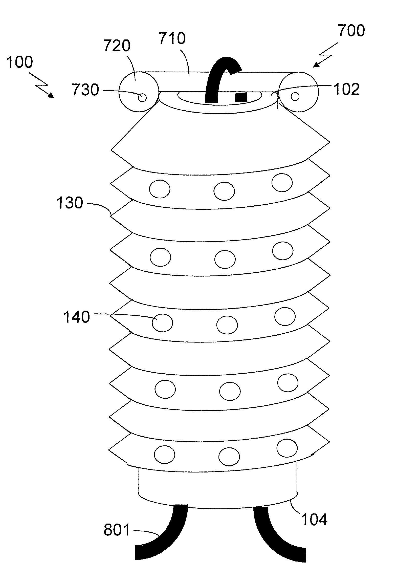
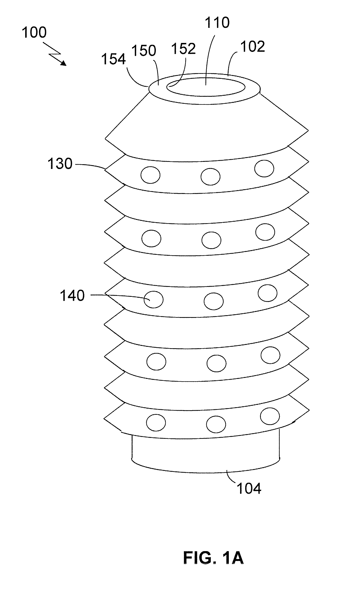
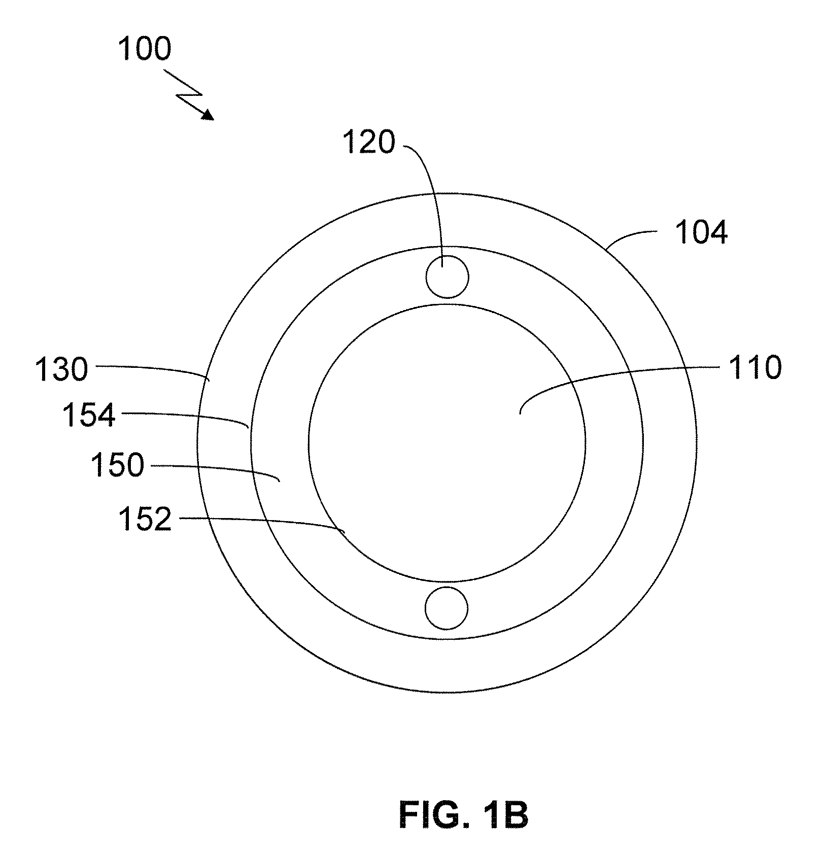
[0045]FIG. 1A is a side view and 1B is a trailing end view of a cannulated screw 100 having a cannula 110 extending from a leading end 102 to a trailing end 104 of the cannulated screw 100 through a cylindrical wall 150 having an inner surface 152 and an outer surface 154, two prong portals 120, threads 130, and optional perforations 140. The cannulated screw 100 may be formed of metal, such as stainless steel or titanium, a biodegradable material, such as a biodegradable polymer, or a combination of the two for...


PUM


Abstract

Various embodiments described herein provide methods and apparatus for achieving the secure and stable fixation of a graft ligament within a bone tunnel using a screw that includes a cylindrical wall having a leading end and a trailing end, threads arranged on an outside surface of the cylindrical wall, and a plurality of portals arranged in the cylindrical wall and adapted to receive a plurality of prongs of a screwdriver.

Description

FIELD OF THE INVENTION[0001]Generally, embodiments disclosed herein relate to systems and methods for attaching a graft ligament to a bone.BACKGROUND OF THE INVENTION[0002]Ligaments are strong fibrous bands of tissue that serve to connect the articular extremities of bones to each other. Ligaments are typically composed of coarse bundles of dense white fibrous tissue that are disposed in a parallel or closely interlaced manner. The fibrous tissue of ligaments is pliant and flexible, but not significantly extensible (stretchable). Ligaments may be torn or ruptured as a result of accidents. The ligaments of the knee joint are especially susceptible to injury and may be repaired using arthroscopic surgical procedures.[0003]For example, in the human knee, the anterior cruciate ligament (ACL) and posterior cruciate ligament (PCL) extend between the top end (proximal end) of the tibia and the bottom end (distal end) of the femur. The ACL and PCL cooperate, together with other ligaments an...

Claims


Application Information

Patent Timeline
IPC IPC(8): A61F2/08A61B17/56
CPCA61B17/1604A61B17/1675A61B17/861A61B17/8645A61B17/8877A61F2002/0882A61F2002/0829A61F2002/0835A61F2002/0852A61F2002/0858A61F2002/0864A61F2/0811
Inventor MANDERSON, EASTON L.
Owner MANDERSON EASTON L
Learn More