
Method for cleaning an oil field capillary tube

a capillary tube and oil field technology, applied in the direction of hollow article cleaning, borehole/well accessories, survey, etc., can solve the problems of capillary tube prone to clogging, substantial loss of revenue, capillary tube clogging again, etc., to maintain formulation stability and minimal metal loss

Inactive Publication Date: 2009-09-24
CHAMPION TECH
View PDF13 Cites 10 Cited by
  • Summary
  • Abstract
  • Description
  • Claims
  • Application Information

AI Technical Summary

Benefits of technology

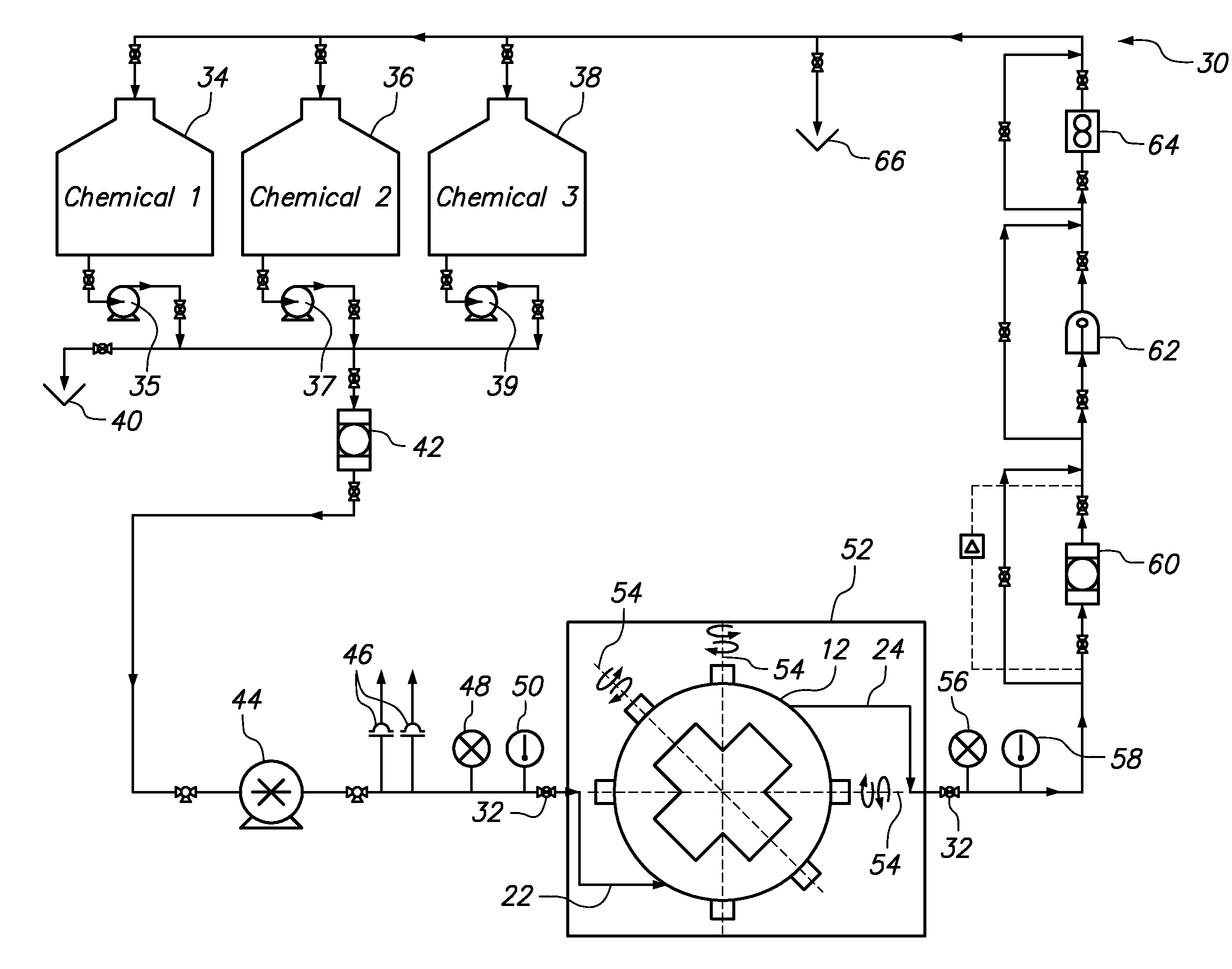
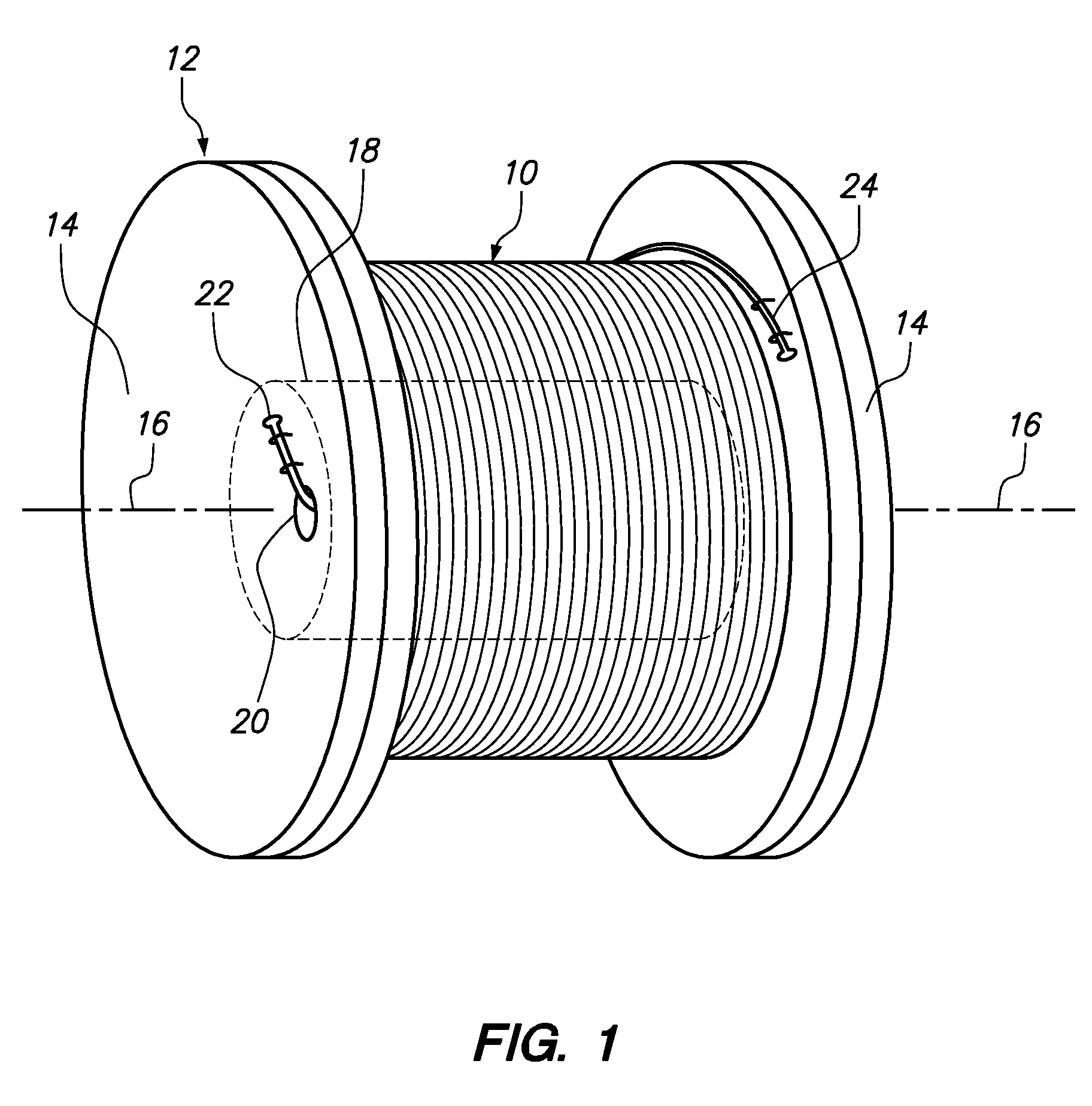
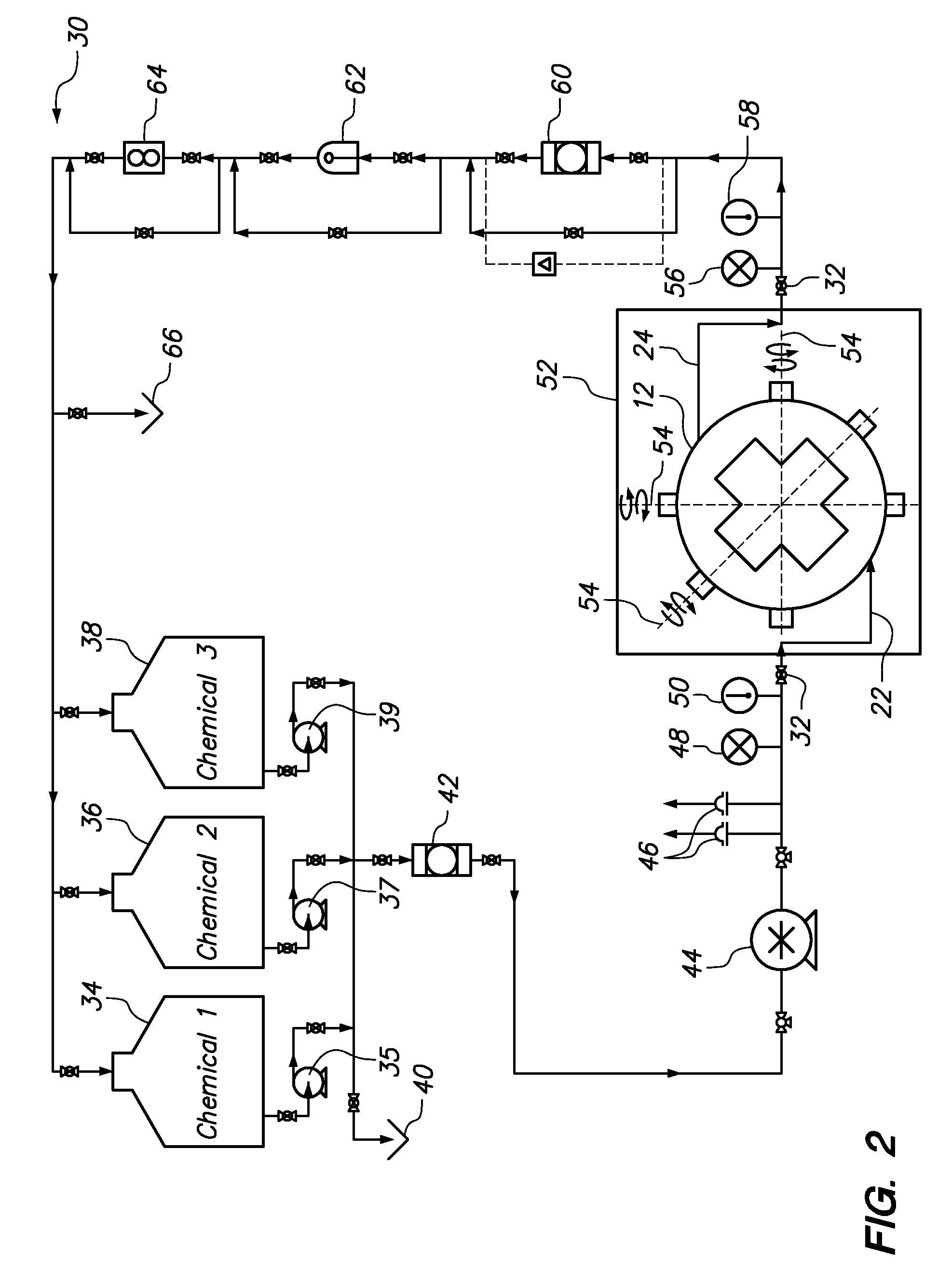
[0011]One embodiment of the invention provides a method and apparatus for removing deposits formed within a capillary tube that has been used to deliver treatment chemicals into a well. The method includes pumping a cleaning solution through the capillary tube coil (after the capillary tube has been removed from the well and is directed to form a coil for cleaning purposes). The cleaning solution comprises at least 20 weight percent of a surfactant or dispersant, at least 5 weight percent of a coupling agent, and at least 10 weight percent solvent. A preferred surfactant or dispersant is selected from the group consisting of an alkyl-aryl sulphonate and a phosphate ester. Dodecylbenzenesulphonic acid is particularly preferred. Depending on the pH of the cleaning formulation, surfactants ...

Problems solved by technology

However, capillary tubes are prone to plugging.
When the desired treatment chemicals are no longer added to the wellbore, production rates can drop significantly or even come to a halt and cause a substantial loss of revenue.
As a result, simply unplugging a capillary tube using a high pressure fluid was found to leave solid deposits over large amounts of surface area within the capillary tube, and these deposits could quickly cause the capillary tube to again become plugged.

Method used


Image

  • Method for cleaning an oil field capillary tube
  • Method for cleaning an oil field capillary tube
  • Method for cleaning an oil field capillary tube

Examples


Embodiment Construction

[0016]The present inventors have discovered that the solids that restrict and plug a capillary tube are formed from combinations of well treatment fluids that were previously believed to be stable under a full range of operating conditions. Now it has been discovered that well treatment fluids may experience conditions in which the combinations of well treatment chemicals interact to form solids that adhere to the inside surface of a capillary tube. The conditions that give rise to the formation of solids in a capillary tube may not be uniformly experienced in all fields, in all wells within a field, or at all positions within a single capillary tube. For example, the hardness of the source of water used to blend with the treatment chemicals may affect solids formation. Furthermore, the temperature of the well treatment fluids rises considerably with the increasing depth of the capillary tube and the depth of the wells can vary significantly. Still further, variations between produc...


PUM


Abstract

A method and apparatus for removing deposits formed within a capillary tube that has been used to deliver treatment chemicals into a well. The method includes pumping a cleaning solution through the capillary tube coil, preferably after the capillary tube has been removed from the well and formed as a coil. The cleaning solution comprises at least 20 weight percent of a surfactant or dispersant, at least 5 weight percent of a coupling agent, and at least 10 weight percent solvent. A preferred surfactant or dispersant is selected from the group consisting of an alkyl-aryl sulphonate and a phosphate ester. An example of a cleaning solution includes dodecylbenzeneylsulphonic (DDBSA) acid, ethylene glycol monobutyl ether and toluene.

Description

CROSS-REFERENCE TO RELATED APPLICATIONS[0001]This application claims priority to U.S. provisional patent application 61 / 037,733, filed on Mar. 19, 2008.BACKGROUND OF THE INVENTION[0002]1. Field of the Invention[0003]The present invention relates to methods for cleaning and maintaining an oil field capillary tube.[0004]2. Description of the Related Art[0005]Capillary tubes are used in oil field applications to inject various treatment chemicals into a production well. A capillary tube typically has a diameter from about one eighth (0.125) inch to about 2 inches and may extend several thousand feet down into a wellbore. Treatment chemicals are pumped into one end of the capillary tube at the surface and exit the other end of the capillary tube situated deep in the wellbore, or at a subsea tree in the case of an offshore subsea design. Accordingly, the treatment chemicals are allowed to contact the production fluids, wellbore casing, and other equipment associated with the production s...

Claims


Application Information

Patent Timeline
IPC IPC(8): E21B47/06E21B47/10
CPCB08B9/027E21B37/06E21B19/22
Inventor ALAPATI, RAMA R.
Owner CHAMPION TECH
Learn More