
Aerosolisation system

a technology of aerosolisation system and feed system, which is applied in the direction of medical inhalators, inhalators, other medical devices, etc., can solve the problems of inability to integrate systems, inability to provide gravity feed with the required flow accuracy, and inability to provide the required flow accuracy

Inactive Publication Date: 2009-09-24
STAMFORD DEVICES LTD
View PDF8 Cites 35 Cited by
  • Summary
  • Abstract
  • Description
  • Claims
  • Application Information

AI Technical Summary

Benefits of technology

[0010]In one embodiment the apertures in the vibratable member are sized to aerosolise fluid by ejecting droplets of the water such that the majority of the droplets by mass have a size of less than 5 micrometers.
[0011]In one case the system comprises a controller for...

Problems solved by technology

There are no integrated systems where the delivery of the liquid to the vibrating mesh is finely controlled at a pre-determined rate.
Gravity feed does not have the required flow accuracy and coupling to external infusion pumps is expensive and cumbersome.

Method used


Image

  • Aerosolisation system
  • Aerosolisation system
  • Aerosolisation system

Examples


Embodiment Construction

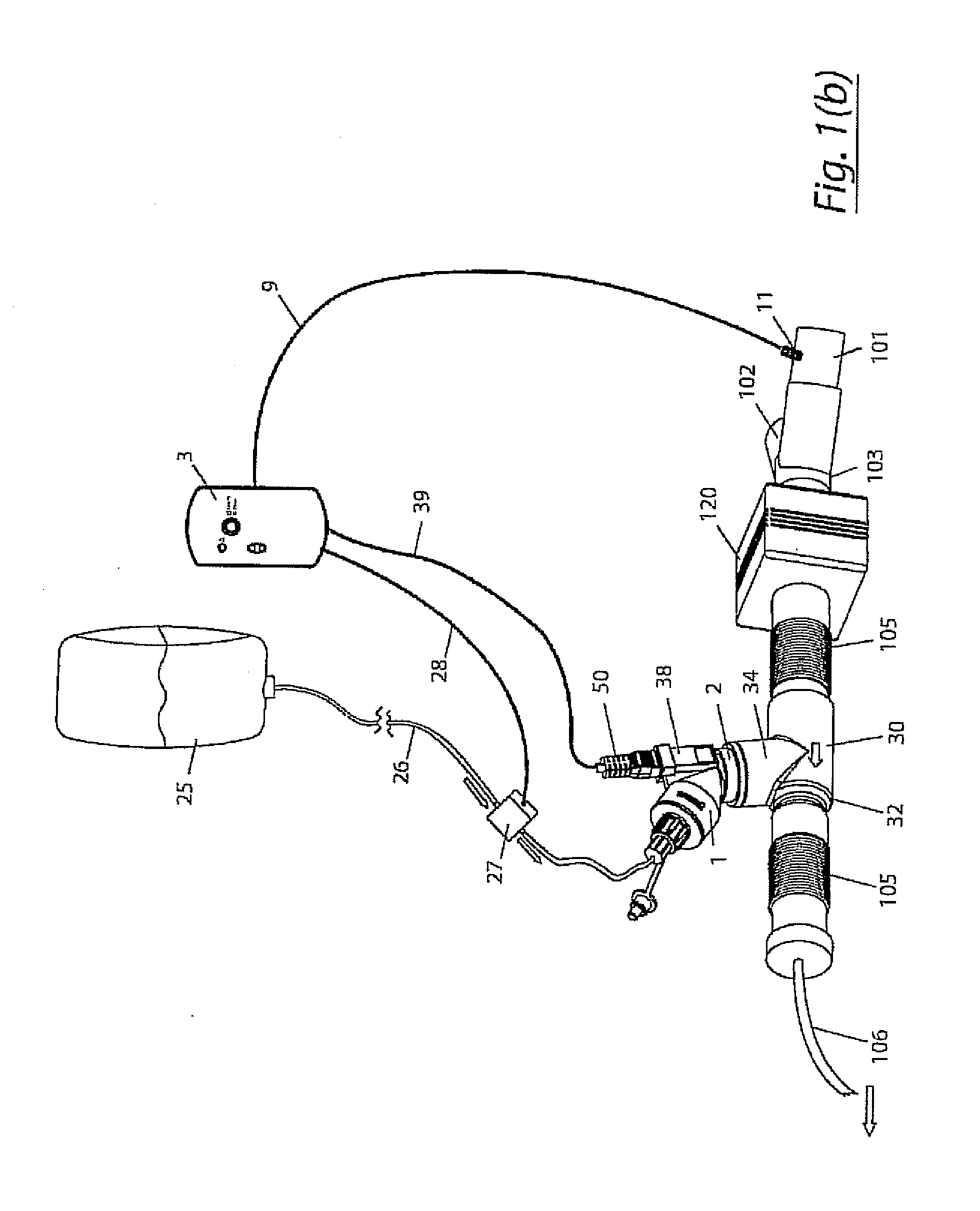
[0032]The invention provides a combination of a micro pump with a vibrating mesh nebuliser. This is powered by a controller. The controller may have modifications to provide the electrical drive mechanism for the pump in addition to fulfilling the aerosol / nebuliser drive requirements.

[0033]The vibrating mesh aerosol generator can work with many types of micro pumps. Flow rates of pumps depend on the application and aerosol output requirements however they are typically in the range of 50 nano litres per minute to 5 millilitres per minute. Such micro pumps can have different means of providing the pumping action and can include membrane pumps, electrohydrodynamic (EHD) pumps, electrokinetic, (EK) pumps, rotary pumps, peristaltic pumps, phase change pumps, and several other types of pumps. Diaphragm pumps that are driven by piezo activation are of particular interest as much of the control circuitry utilised is similar to that used to drive vibrating mesh technology and therefore inte...


PUM


Abstract

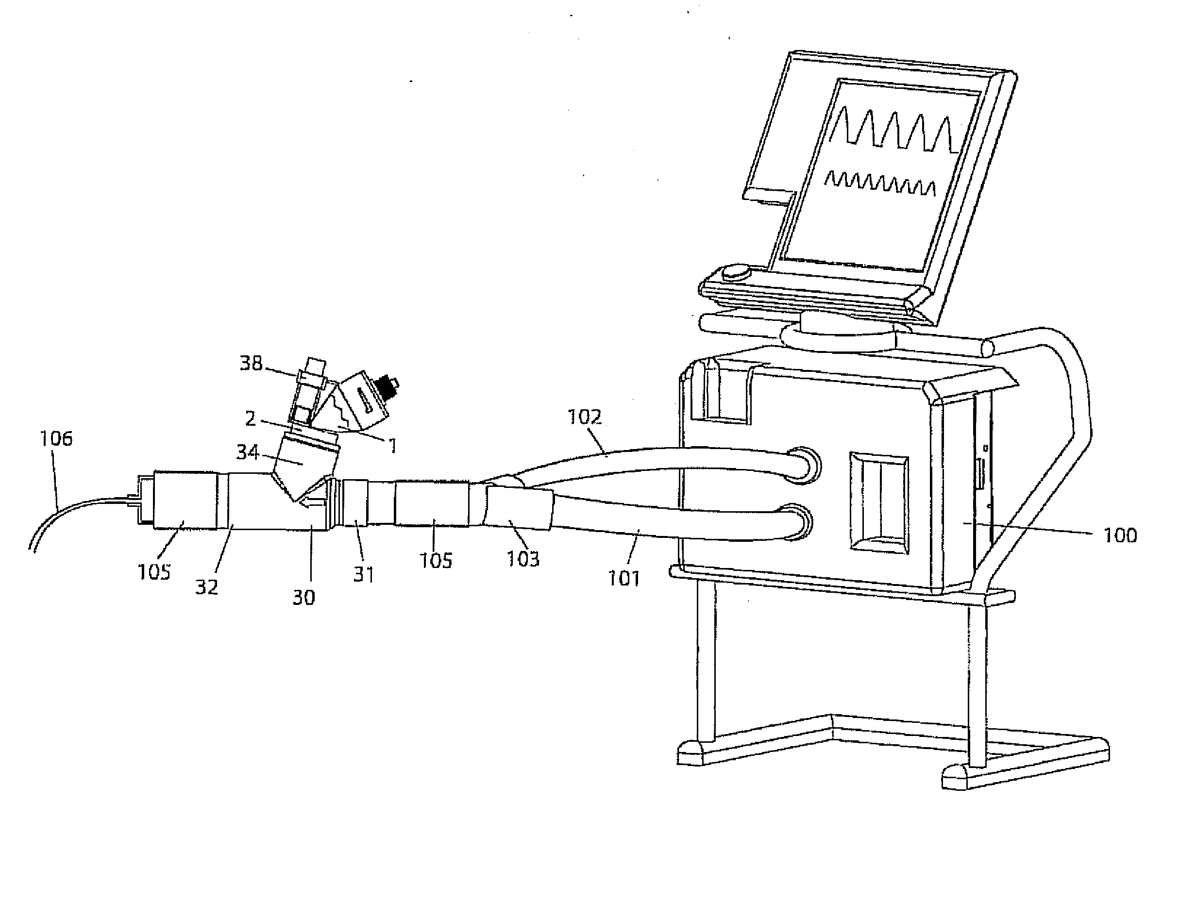
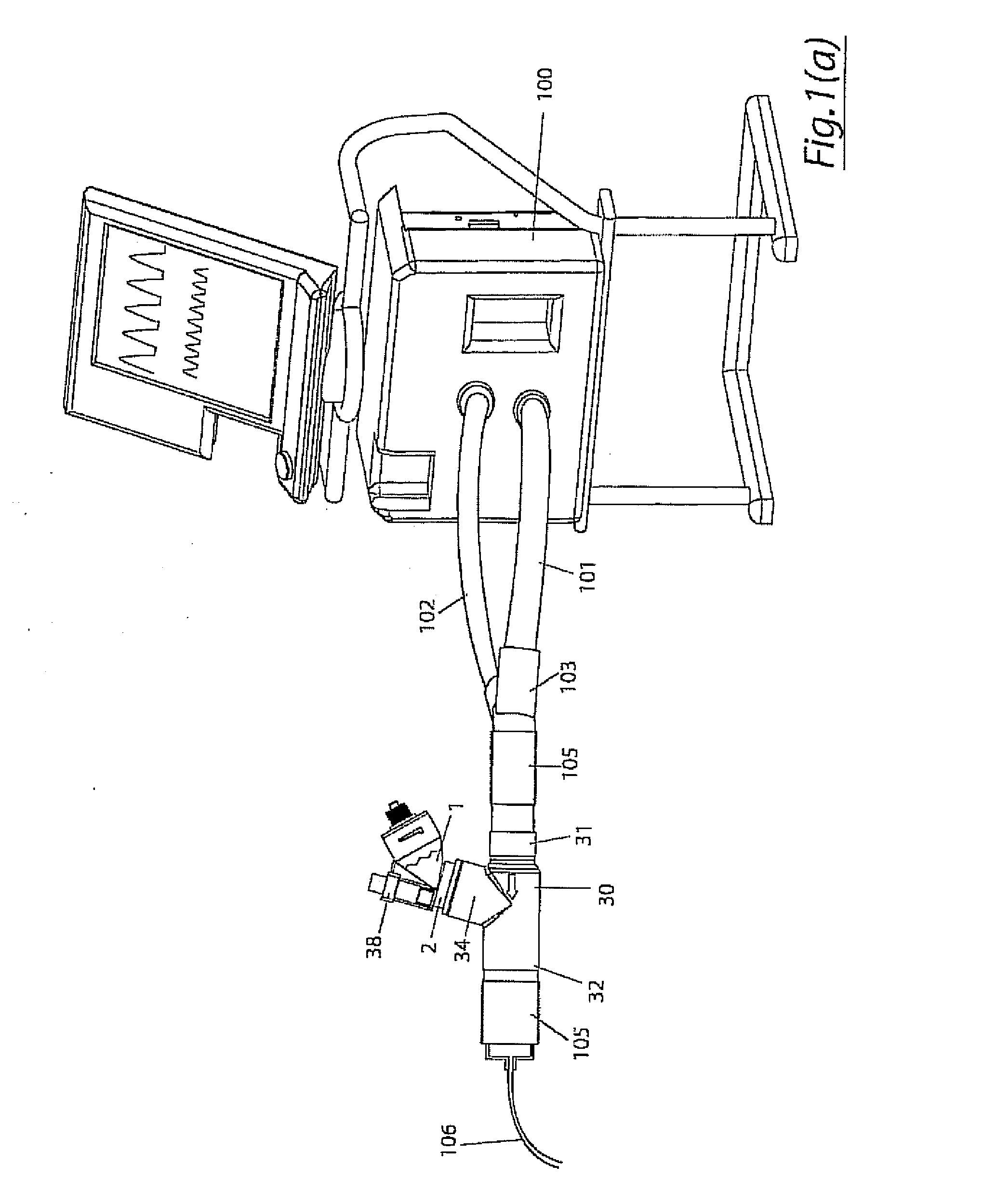
The invention provides a combination of a micro pump 27 or a micro valve with a vibrating mesh nebuliser 2. This is powered by a controller 3. The controller 3 may have modifications to provide the electrical drive mechanism for the pump 27 in addition to fulfilling the aerosol / nebuliser drive requirements. In one case the system is used for humidifying gas in a ventilator circuit. A humidifying agent (sterile water or sterile saline) is aerosolised and then delivered to a ventilator circuit 100 coupled to the respiratory system of a patient.

Description

CROSS-REFERENCES TO RELATED APPLICATIONS[0001]The present application is a continuation-in-part of U.S. patent application Ser. No. 12 / 058,255 filed Mar. 28, 2008 which claims the benefit of U.S. provisional Application No. 60 / 907,311 filed Mar. 28, 2007 and also a continuation-in-part of U.S. patent application Ser. No. 12 / 058,304 filed Mar. 28, 2008 which claims the benefit of U.S. provisional Application No. 60 / 907,311 filed Mar. 28, 2007. The present application also claims the benefit of U.S. provisional application No. 61 / 073,582 filed Jun. 18, 2008; U.S. provisional application No. 61 / 100,510 filed Sep. 26, 2008; and U.S. provisional application No. 61 / 100,515 filed Sep. 26, 2008.[0002]The complete disclosures of all of these are incorporated herein by reference.BACKGROUND OF THE INVENTION[0003]The invention relates to aerosol delivery control and feed systems.[0004]Aerosol output of existing vibrating mesh technologies is inherently variable between devices. If input power c...

Claims


Application Information

Patent Timeline
IPC IPC(8): A61M11/00
CPCA61B17/3474A61M16/0009A61M13/003A61M15/0085A61M16/1045A61M16/14A61M16/16A61M2016/0039A61M2202/0208A61M2202/0225A61M2202/025A61M2202/0266A61M2202/0291A61M2202/0468A61M2202/048B05B7/0075B05B17/0646B05B17/0669A61M13/00A61M16/1055A61M16/107A61M16/0833B05B12/081
Inventor POWER, JOHN SYLVESTERGIBBONS, KEITHDUFFY, CONOR PAULSMITH, NIALLCLANCY, DERMOT
Owner STAMFORD DEVICES LTD
Learn More