
Optical analysis device

an optical analysis and optical technology, applied in the direction of material analysis, radiation pyrometry, instruments, etc., can solve the problems of high energy consumption, aging-induced intensity attenuation of radiation sources, and inability to detect only one detector, so as to achieve the lowest possible diffusion time and increase the effect of security

Active Publication Date: 2009-09-24
GFG GES FUR GERATEBAU
View PDF5 Cites 6 Cited by
  • Summary
  • Abstract
  • Description
  • Claims
  • Application Information

AI Technical Summary

Benefits of technology

[0015]Optionally, a reference channel through a first detector can be used at both detector positions. If the danger of inhomogeneous contamination is low, just one reference channel suffices.
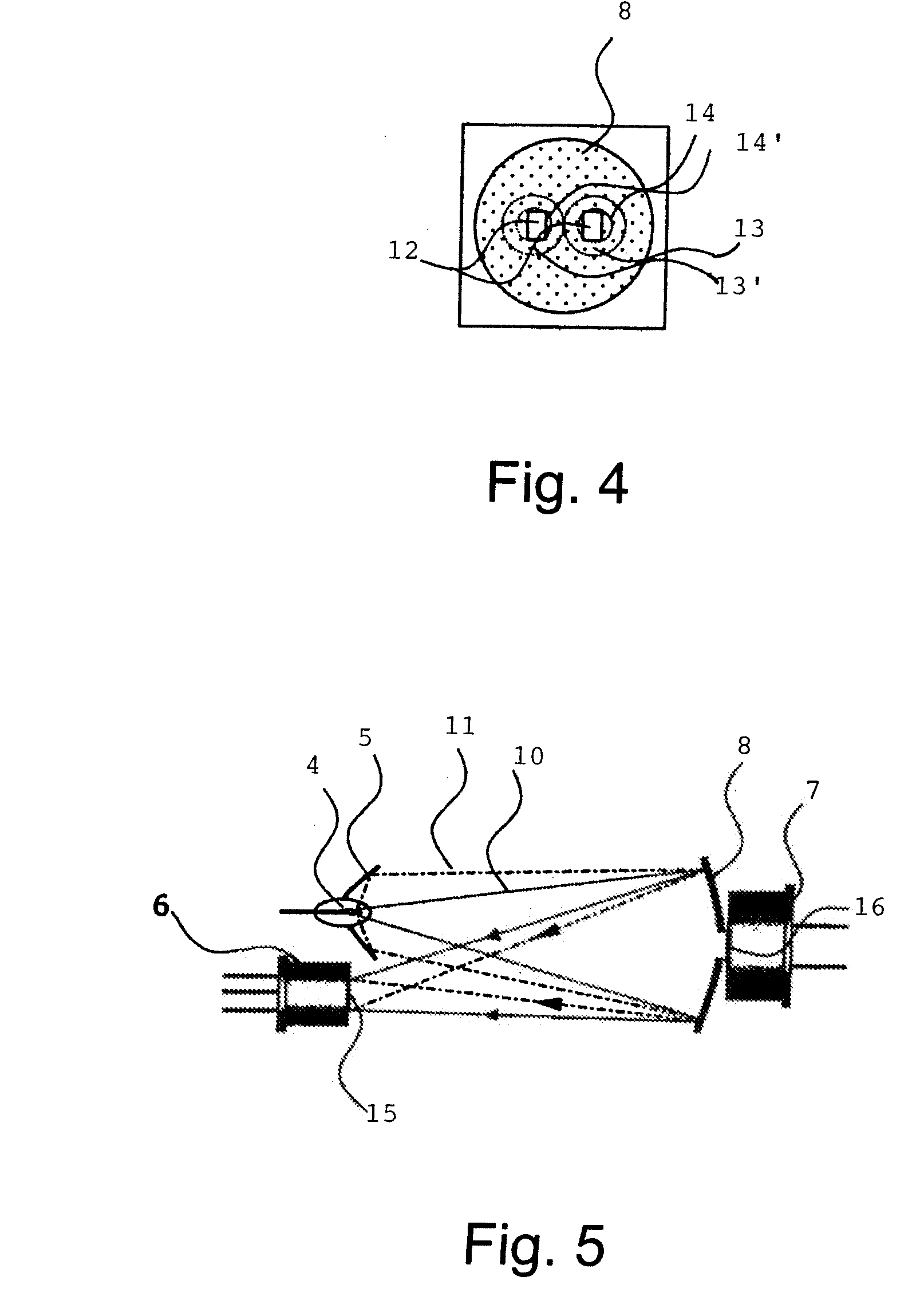
[0017]In the external reflector, the mirror surface is formed so that an as large as possible portion of the impacted radiation is directed to the first and second detector. In a simple design, this can be a spherical mirror, in particular, a globe mirror for illuminating a symmetrical detector. The mirrors can be optimized so that both the beams that are only reflected from the external reflector as well as those from the reflector assigned to the radiation source and reflected from the external reflector illuminate the detectors well.
[0022]The remaining construction of the device can be designed so that lowest possible diffusion times for the material exchange can be obtained. In particular, the absorption space can be protected against contamination using a membrane permeable to gas. As an alternative, the analysis device can be protected against explosion; for example, the absorption space can be protected by a flame trap, e.g., sintered metal, a corresponding housing and a casting. The constructive requirements for explosion protection “d” are stated in IEC 60079-1. It is also possible to combine two independent types of ignition protection redundantly to increase the security and to make execution possible in ex-zone 0.

Problems solved by technology

To the same degree, for example, aging-induced intensity attenuation of the radiation source also cannot be detected with only one detector.
The arrangement is relatively space consuming and expensive due to the annular arrangement of the detectors having more or less each straight-line, unfolded radiation paths.
In this arrangement, too, only a small portion of the radiation reaches the detectors, so that the result is a high consumption of energy.
Moreover, there is a problem in that only weakly absorbing components require a longer absorption path compared to strongly absorbing components in order to maintain an identically strong signal at the same material concentration.

Method used


Image

  • Optical analysis device
  • Optical analysis device
  • Optical analysis device

Examples


Embodiment Construction

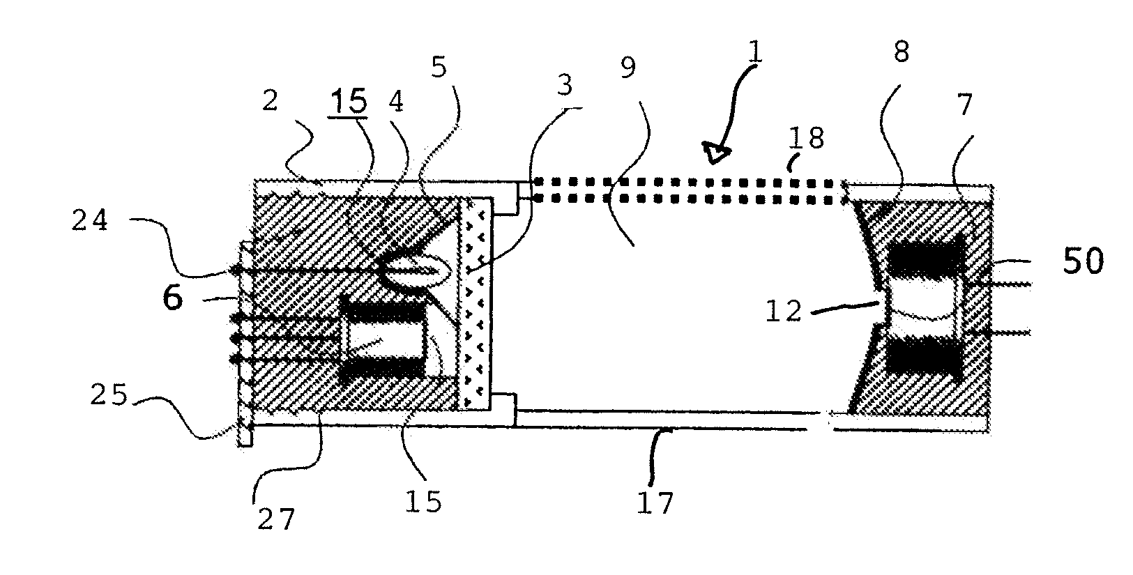
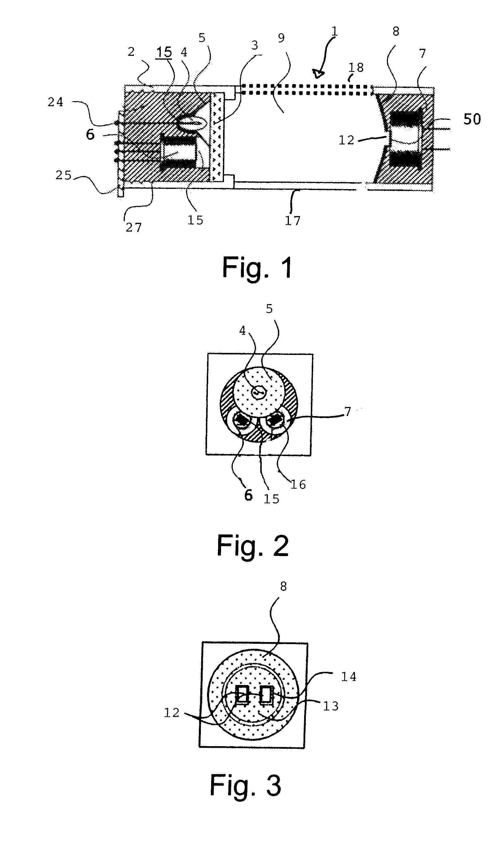
[0032]An optical analysis device 1 operating according to the principle of radiation absorption has a housing 2 with at least one radiation-permeable housing element 3 as well as a radiation source 4 and a reflector 5 assigned to it as well as at least one first detector 6 and a second detector 7 and an external reflector 8 located outside the housing 2. An absorption space 9 is bounded by the radiation-permeable housing element 3 and the external reflector 8 as well as side walls 17, 18.

[0033]A measuring beam emitted from the radiation source 4 and is reflected back into the housing 2 after reflection by the external reflector 8, as is indicated FIG. 5 by the reference number 11, while a measuring beam 10 coming from the radiation source 4 is not reflected by the associated reflector 5, but is only reflected by the external reflector 8 (path shown by broken lines in FIG. 5). The external reflector 8 has at least one non-reflecting recess 12 according to the invention. A third detec...


PUM


Abstract

An optical analysis device that operates according to the principle of radiation absorption, has a housing (2) with at least one radiation-permeable housing element (3), at least one radiation source (4) having a reflector (5) associated with it, at least a first detector (6) and a second detector (7) as well as an external reflector (8) located outside the housing (2), wherein an absorption space is formed by the external reflector (8) and the radiation-permeable housing element (3), and a measuring beam (10) emitted by the radiation source (4) and the reflector (5) returns to the housing (2) again after being reflected by the external reflector (8), and wherein the external reflector (8) has at least one recess (12) that does not reflect the measuring beam and behind which a third detector is arranged for receiving the measuring beam.

Description

BACKGROUND OF THE INVENTION[0001]1. Field of Invention[0002]The invention relates to an optical analysis device according to the principle of radiation absorption with a housing having at least one radiation-permeable housing element, with at least one radiation source and a reflector assigned to it, with at least a first detector and a second detector and with an external reflector located outside of the housing. An absorption space is formed by the external reflector and the radiation-permeable housing element, wherein a measuring beam emitted by the first radiation source and the first reflector re-enters the housing after reflection on the external reflector.[0003]2. Description of Related Art[0004]Optical analysis devices of the type under consideration exploit the effect of radiation absorption by matter, which is penetrated by electromagnetic radiation. The electromagnetic radiation is generally broadband and covers at least the frequency range in which the substance to be de...

Claims


Application Information

Patent Timeline
Patent Type & Authority Applications(United States)
IPC IPC(8): G01J5/00G01B9/02
CPCG01N21/0303G01N21/61G01N21/3504
Inventor HUEBNER, JOERGKRAGE, RAINER
Owner GFG GES FUR GERATEBAU
Learn More