Synchronous motor control device and method for optimizing synchronous motor control

a synchronous motor and control device technology, applied in the direction of motor/generator/converter stopper, dynamo-electric gear control, dynamo-electric converter control, etc., can solve the problem of difficult elimination of high-order harmonics by feedback control

Inactive Publication Date: 2009-09-24
AISIN SEIKI KK
View PDF7 Cites 42 Cited by
  • Summary
  • Abstract
  • Description
  • Claims
  • Application Information

AI Technical Summary

Problems solved by technology

Hence, elimination of the high-order harmonic by the feedback control is difficult.

Method used


Image

  • Synchronous motor control device and method for optimizing synchronous motor control
  • Synchronous motor control device and method for optimizing synchronous motor control
  • Synchronous motor control device and method for optimizing synchronous motor control

Examples


Embodiment Construction

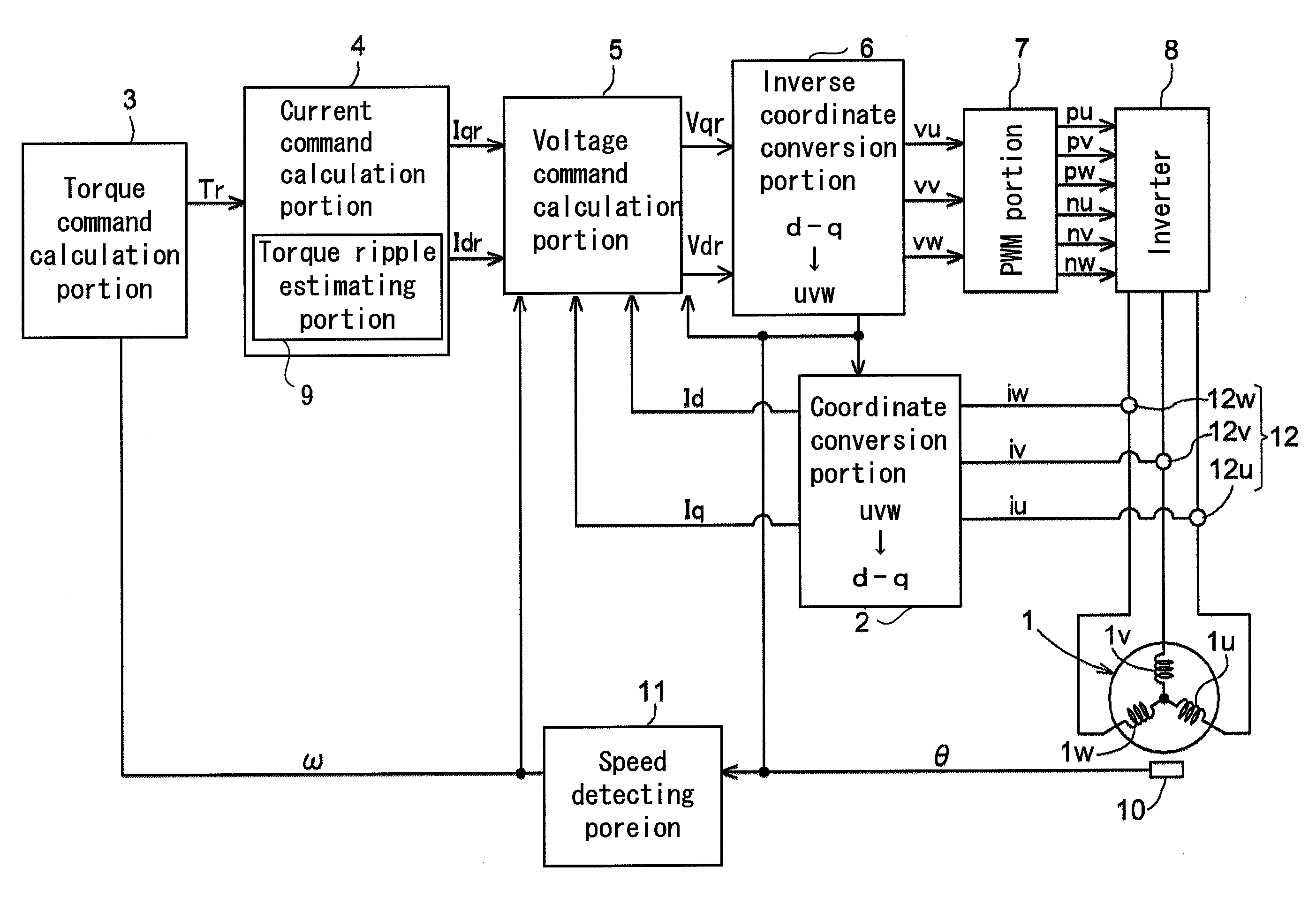
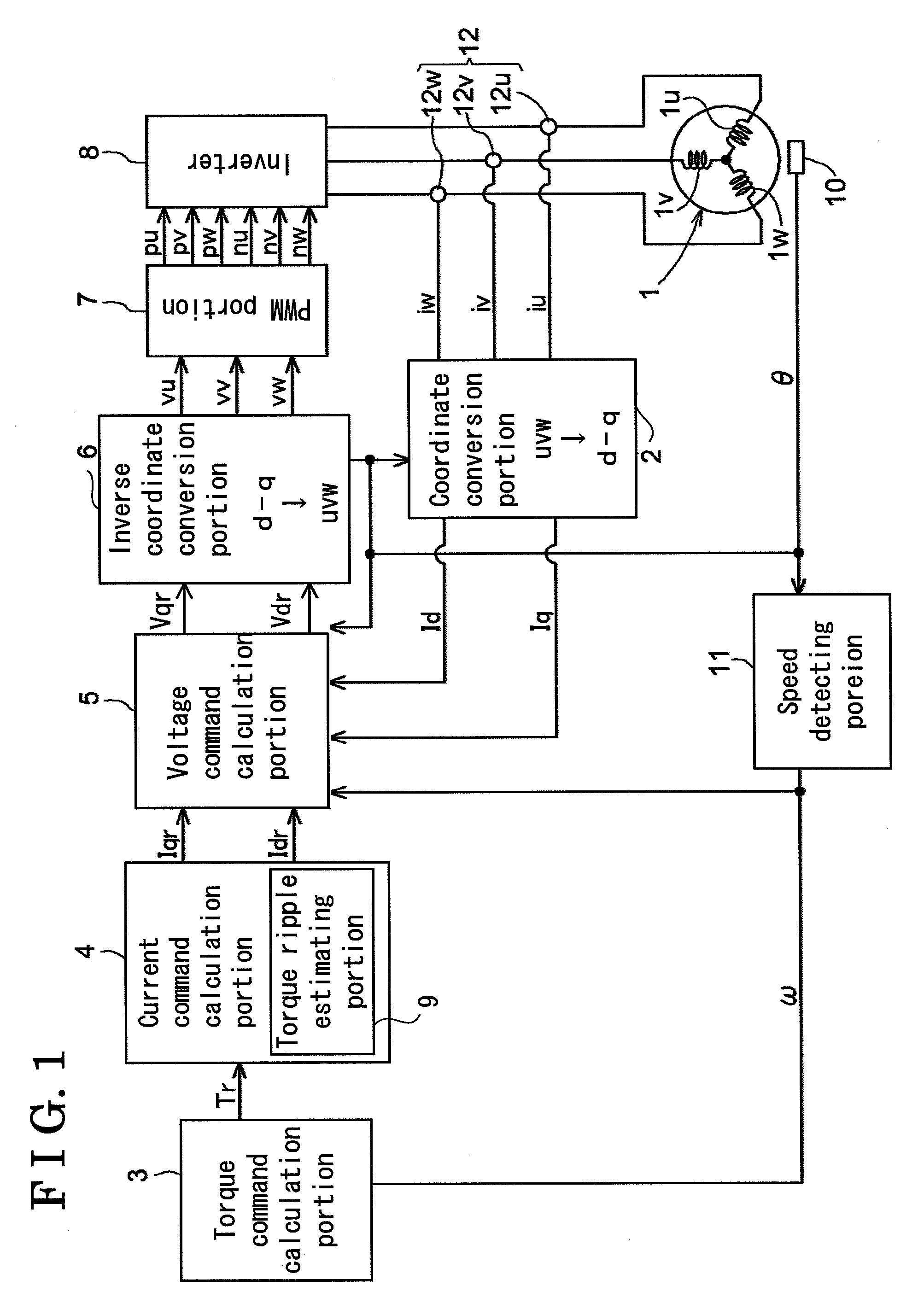
[0029]An embodiment of a synchronous motor control device will be described below in accordance with the attached drawings. FIG. 1 is a block diagram schematically illustrating a configuration example of the synchronous motor control device. A motor 1 is a three-phase synchronous motor. The motor 1 includes a rotor having permanent magnets and a stator that generates a magnetic field for applying a rotational force to the rotor. The stator includes stator coils 1u, 1v and 1w that form U-phase, V-phase and W-phase, respectively. One end of each of the stator coils 1u, 1v and 1w is commonly connected at an electrical neutral point so as to from a Y-connection (a star-connection). The other end of each of the stator coils 1u, 1v and 1w is connected to an inverter 8 that will be described below. As illustrated in FIG. 1, the synchronous motor control device of the embodiment drives the stator coils 1u, 1v and 1w that forms the three-phase via the inverter 8 in response to a target torqu...


PUM


Abstract

A synchronous motor control device, includes a coordinate transformation portion for coordinate transforming motor currents applied to respective three phases of a synchronous motor into a d-axis, corresponding to a direction of a magnetic field generated by a permanent magnet arranged at a rotor of the synchronous motor, and a q-axis orthogonal to the d-axis, a current command calculation portion for calculating a d-axis current command and a q-axis current command from a target torque, a voltage command calculation portion for calculating a d-axis voltage command and a q-axis voltage command, an inverse coordinate transformation portion for inversely coordinate transforming the d-axis voltage command and the q-axis voltage command into three-phase voltage commands, and a torque ripple estimating portion for estimating a torque ripple and feed-forwarding the estimation results to the current command calculation portion or the voltage command calculation portion.

Description

CROSS REFERENCE TO RELATED APPLICATIONS[0001]This application is based on and claims priority under 35 U.S.C. § 119 to Japanese Patent Application 2007-138007, filed on May 24, 2007, the entire contents of which is incorporated herein by reference.FIELD OF THE INVENTION[0002]The present invention relates to a synchronous motor control device and a method for optimizing synchronous motor control.BACKGROUND[0003]A so called ‘vector-control’ is known as a method for controlling a synchronous motor. In the vector-control disclosed in, for example JP 2006320039A, motor current applied through each of three phases of the synchronous motor is coordinate-transformed into a vector component that is transformable into vector components directed along a direct axis (hereinafter referred to as d-axis) corresponding to a direction of a magnetic field generated by permanent magnets arranged at a rotor and a quadrature axis (hereinafter referred to as a q-axis) orthogonal to the d-axis, and then a...

Claims


Application Information

Patent Timeline
Patent Type & Authority Applications(United States)
IPC IPC(8): H02P21/05H02P21/13H02P21/00H02P21/14H02P23/04H02P23/14H02P27/04
CPCH02P21/145H02P21/16
Inventor YAMADA, NAOKI
Owner AISIN SEIKI KK
Why Eureka
Try Eureka