Eureka AIR delivers breakthrough ideas for toughest innovation challenges, trusted by R&D personnel around the world.

Batteries and Battery Monitoring and Charging Systems

Inactive Publication Date: 2009-09-24
LENDER COLLECTIONS
View PDF3 Cites 20 Cited by
  • Summary
  • Abstract
  • Description
  • Claims
  • Application Information

AI Technical Summary

Problems solved by technology

First, the power output terminals of the battery must be readily accessible, creating a possible safety hazard on the inadvertent shorting of those power terminals.
Also batteries typically are comprised of multiple cells connected in series, so that individual cells cannot be monitored through its power output terminals.

Method used


Image

  • Batteries and Battery Monitoring and Charging Systems
  • Batteries and Battery Monitoring and Charging Systems
  • Batteries and Battery Monitoring and Charging Systems

Examples


Embodiment Construction

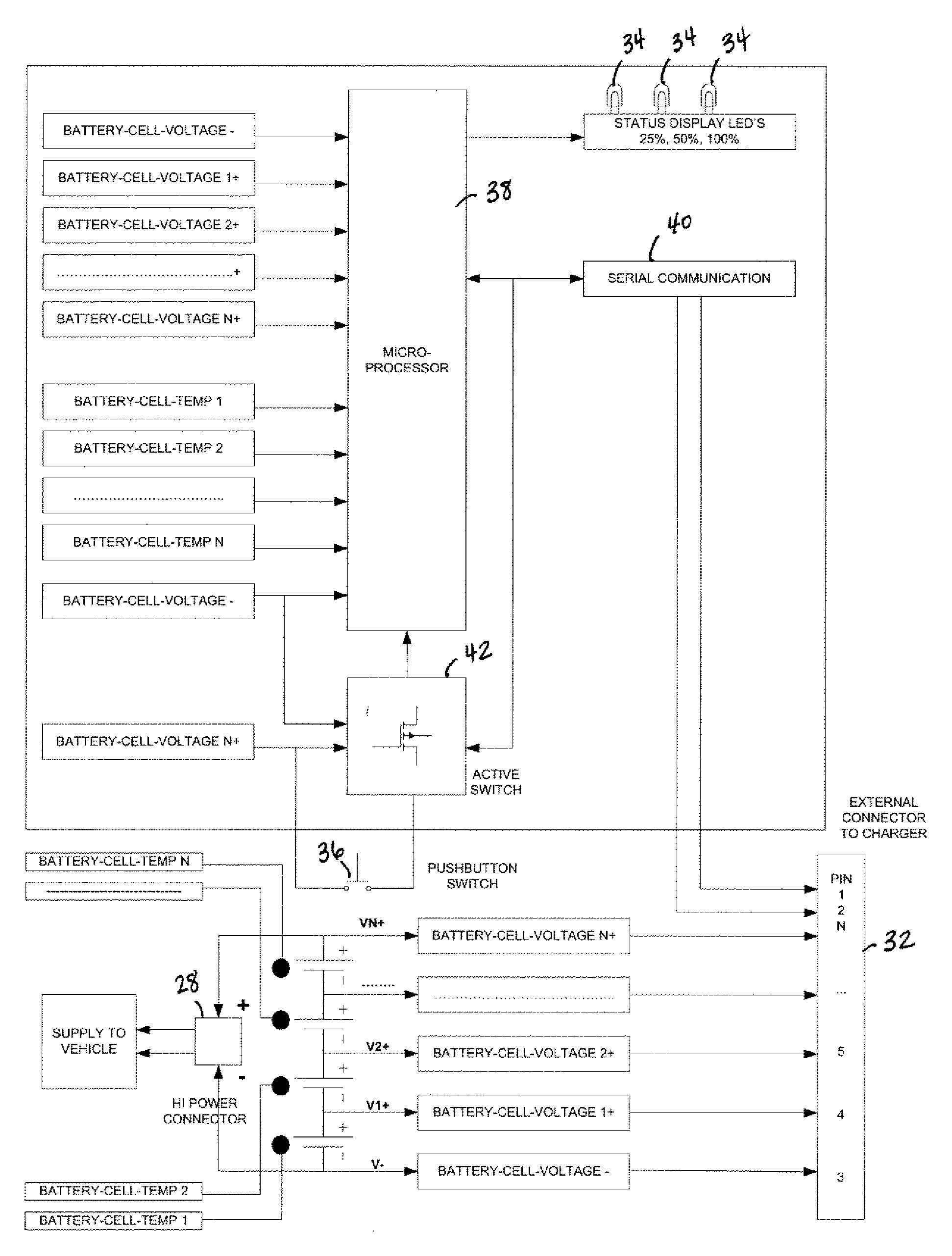
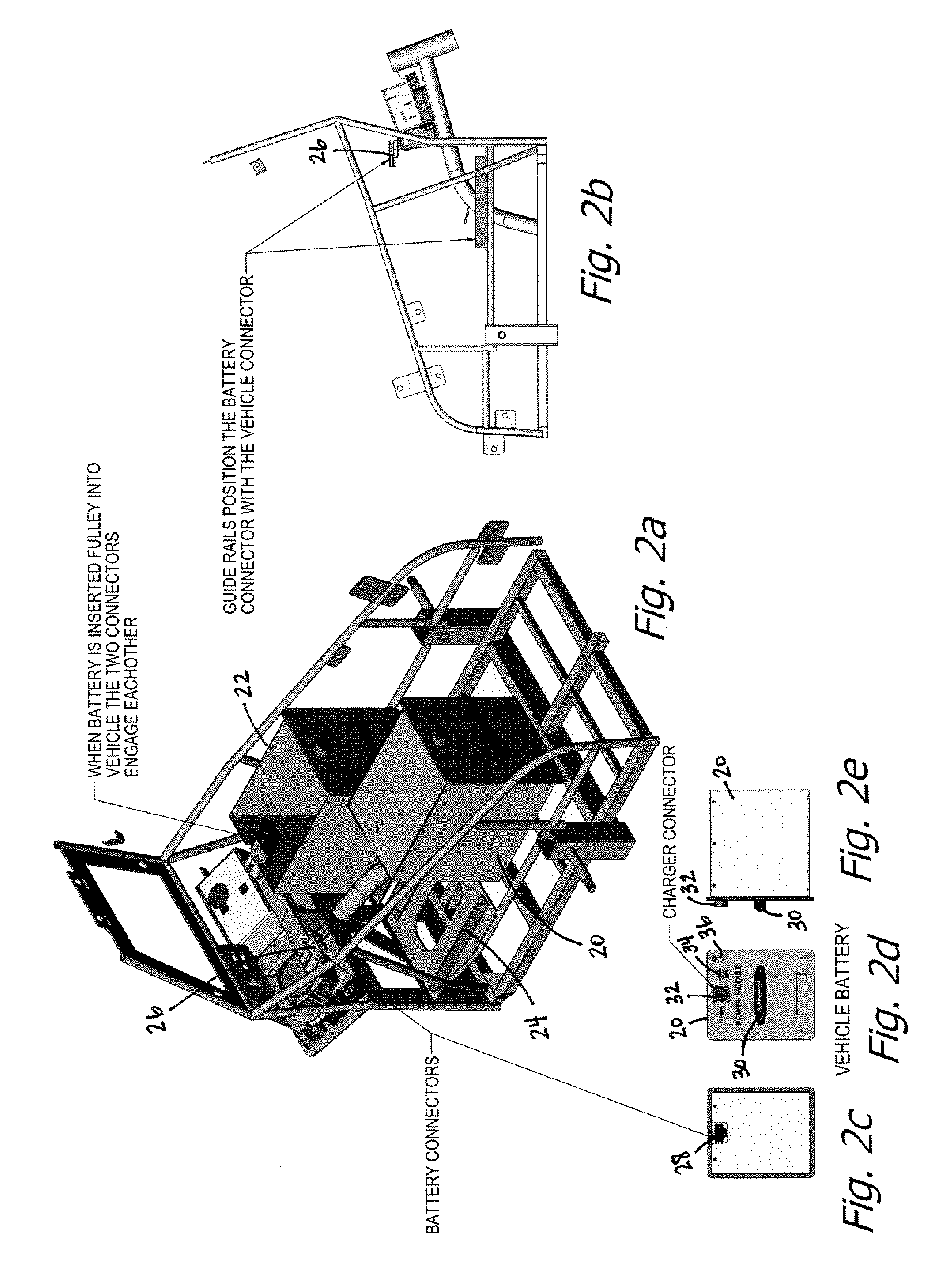
[0013]FIG. 2a is a perspective view of the chassis of the vehicle of FIGS. 1a and 1b, with FIG. 2b being a side view of the chassis. FIG. 2a shows a complete battery 20 and a battery container 22, the vehicle of FIGS. 1a and 1b using two batteries for the operation thereof. The batteries 20 are aligned and slide into the vehicle on guides 24, and when slid to their forward most position, make contact with connectors 26 fastened to the chassis. In that regard, a typical battery 20 may be seen in FIGS. 2c, 2d and 2e. FIG. 2c is a view of a battery from the back, FIG. 2d a front view of the battery and FIG. 2e a side view of the battery. It will be noted that the power connector 28 within the battery, as shown in FIG. 2c, does not project outward from the back of the battery as may be seen in FIG. 2e, but rather is recessed for protection and to avoid inadvertent shorting of the battery terminals and the hazards presented thereby. At the front of the battery 20 is a handle 30, a monito...


PUM


Abstract

Batteries and battery monitoring and charging systems. The preferred battery has a plurality of rechargeable cells connected in series, first and second power terminals, each connected to a respective end of the series connection of rechargeable cells, a first connector for connecting to a battery charger, the first connector having connector contacts connected to each of the plurality of rechargeable cells, the first connector also having connector contacts coupled to a serial communication link, and a processor coupled to sense the voltage of each rechargeable cell and control the serial communication link for communication of rechargeable cell voltages when a charger is connected to the first connector. The charger communicates with the battery over the serial communication link to monitor cell temperature, and to charge each cell individually in a controlled manner. Various features and capabilities are disclosed.

Description

BACKGROUND OF THE INVENTION[0001]1. Field of the Invention[0002]The present invention relates to the field of battery powered vehicles.[0003]2. Prior Art[0004]Battery powered vehicles of various sizes and designs are well known in the prior art. Of particular interest to the present invention are the smaller vehicles wherein the battery may be recharged in the vehicle or removed for recharging while another battery is placed in the vehicle so that the vehicle may be used while recharging occurs. One such vehicle is the three-wheeled vehicle shown in FIGS. 1a and 1b. This vehicle is manufactured by T3 Motion, Inc., assignee of the present invention.[0005]In small electric powered vehicles using a removable rechargeable battery, the battery typically is recharged through its power output terminals, whether in the vehicle or removed from the vehicle for recharging. This provides a simple and low cost way of recharging such batteries, though has certain disadvantages. First, the power o...

Claims


Application Information

Patent Timeline
IPC IPC(8): H02J7/00
CPCH01M10/441H01M10/482Y02T10/7055H01M10/488H02J7/0021H01M10/486Y02T10/70Y02E60/10H02J7/0013H02J7/005H02J7/0049
Inventor NAM, KI Y.CAO, KENNETH TIEN
Owner LENDER COLLECTIONS
Why Eureka
Eureka Blog
Learn More