Display controller, display device, display system, and method for controlling display device

a display controller and display device technology, applied in the direction of electric digital data processing, instruments, computing, etc., can solve the problems of display device not correctly obtaining video data, screen disassembly in switching refresh rate, etc., to prevent noise, reduce power consumption, and prevent the effect of disassembly

Inactive Publication Date: 2009-09-24
SHARP KK
View PDF8 Cites 55 Cited by
  • Summary
  • Abstract
  • Description
  • Claims
  • Application Information

AI Technical Summary

Benefits of technology

[0018]The present invention was made in view of the foregoing problems, and a first object of the present invention is to provide a display controller, a display device, and a display system, each of which suppresses occurrence of noise also in switching the refresh rate thereby preventing a screen from being disarranged by the noise, and a second object of the present invention is to provide a display controller, a display device, a display system, and a display device control method, each of which realizes less variation in a charging rate also in switching the refresh rate and allows an image giving the user no unnatural feeling to be displayed.
[0022]The display device has a plurality of pixels, and writing of video data into the pixels causes an image to be displayed on the screen of the display device. Further, the display controller can change a refresh rate indicative of how often a screen displayed on the display device is switched. In this manner, the refresh rate can be changed, so that it is possible to reduce power consumption by adopting not only the high refresh rate mode but also the low refresh rate mode. Further, the horizontal synchronization signal and the vertical synchronization signal are supplied to the display device, so that a single horizontal period and a single vertical period can be defined on the side of the display device. As a result, a predetermined image based on the video data can be displayed on the screen.
[0023]Particularly, according to the foregoing arrangement, there is provided the dot clock generation device to generate the dot clock (reference clock), supplied to the display device, whose frequency is constant without depending on the change of the refresh rate. Further, according to the foregoing method, the dot clock whose frequency is constant is supplied to the display device without depending on the change of the refresh rate. Thus, in case where the refresh rate is switched from the high refresh rate mode to the low refresh rate mode and in case where the refresh rate is switched from the low refresh rate mode to the high refresh rate mode, the dot clock does not change. Thus, it is possible to prevent occurrence of noise caused by the change of the dot clock and prevent disarrangement of the screen which is caused by the noise.
[0026]The display device has a plurality of pixels, and writing of video data into the pixels causes an image to be displayed on the screen of the display device. Further, the display controller can change a refresh rate indicative of how often a screen displayed on the display device is switched. In this manner, the refresh rate can be changed, so that it is possible to reduce power consumption by adopting not only the high refresh rate mode but also the low refresh rate mode. Further, the horizontal synchronization signal and the vertical synchronization signal are supplied to the display device, so that a single horizontal period and a single vertical period can be defined on the side of the display device. As a result, a predetermined image based on the video data can be displayed on the screen.

Problems solved by technology

However, if the refresh rate is changed from a 60 Hz mode to a 40 Hz mode or the refresh rate is changed from the 40 Hz mode to the 60 Hz mode, this raises the following two problems (a) and (b).
With the change of the dot clock, noise occurs in changing the refresh rate is from the 60 Hz mode to the 40 Hz mode and in switching the mode so that the refresh rate is changed from the 40 Hz mode to the 60 Hz mode, and the noise may cause the screen to be disarranged in switching the refresh rate.
If the dot clock suddenly changes, an operation for sampling video data is incorrectly carried out on the side of the display device, so that the display device fails to correctly obtain the video data.

Method used


Image

  • Display controller, display device, display system, and method for controlling display device
  • Display controller, display device, display system, and method for controlling display device
  • Display controller, display device, display system, and method for controlling display device

Examples


embodiment 1

[0059]One embodiment of the present invention is described below with reference to the attached drawings.

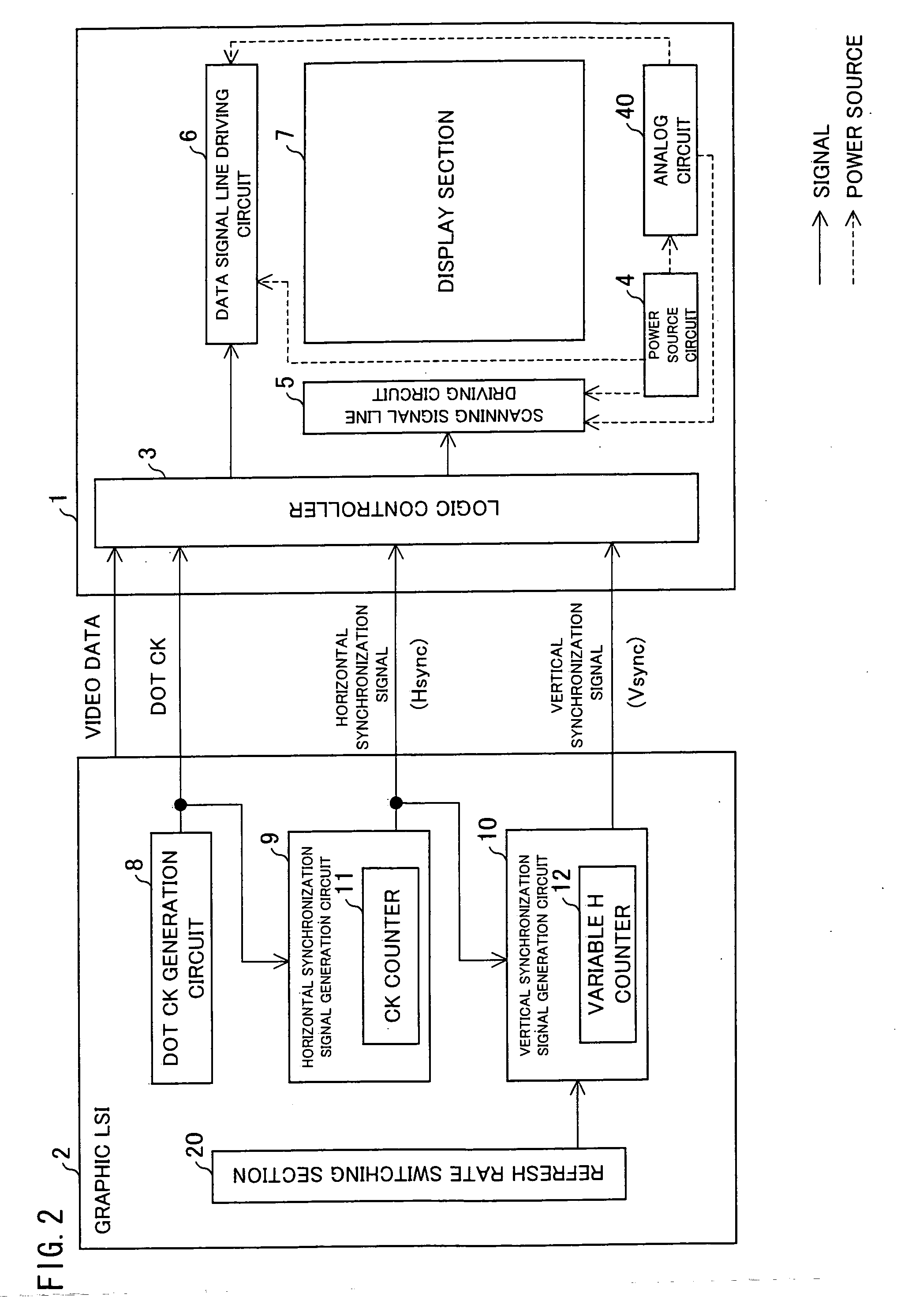
[0060]As illustrated in FIG. 2, a display system of the present embodiment includes a display device 1 and a graphic LSI (display controller) 2 positioned at a preceding stage of the display device 1.

[0061]The display device 1 is a liquid crystal display device for example, and includes: a logic controller (sometimes, referred to merely as “controller”) 3; a power source circuit 4; a scanning signal line driving circuit 5; a data signal line driving circuit 6; a display section 7 for displaying an image; and an analog circuit 40. The power source circuit 4 serves as a driver of the logic controller 3, the scanning signal line driving circuit 5, the data signal line driving circuit 6, and the like. A dotted line of FIG. 2 shows a power supply route. As illustrated in FIG. 2, the power source circuit 4 supplies power to the scanning signal line driving circuit 5, the data signal li...

embodiment 2

[0089]Another embodiment of the present invention is described below with reference to the attached drawings. The present embodiment describes differences from Embodiment 1. Thus, for convenience for description, the same reference numerals are given to members having the same functions as those of Embodiment 1, and descriptions thereof are omitted.

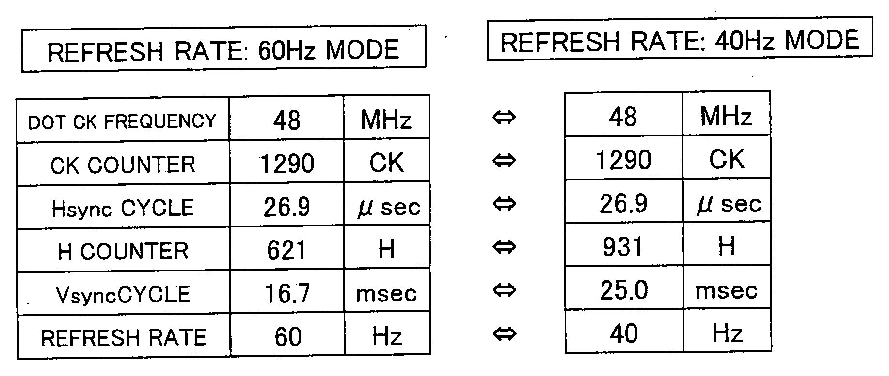
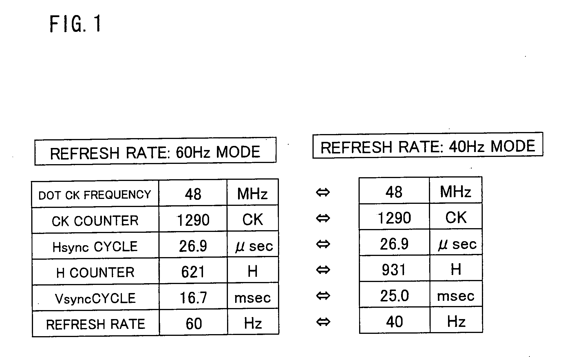
[0090]In Embodiment 1, the first command signal is inputted to the variable H counter 12, and in accordance with the first command signal, the H count number counted by the variable H counter 12 is set to 621 in case where the refresh rate is the normal refresh rate of 60 Hz and the H count number counted by the variable H counter 12 is set to 931 in case where the refresh rate is the low refresh rate of 40 Hz.

[0091]In the present embodiment, the variable H counter 12 receives a second H count number variation command signal (second command signal) for giving an instruction to increase the H count number counted by the variable H counter ...

embodiment 3

[0100]Still another embodiment of the present invention is described below with reference to the attached drawings. The present embodiment describes differences from Embodiments 1 and 2. Thus, for convenience in description, the same reference numerals are given to members having the same functions as those of Embodiments 1 and 2, and descriptions thereof are omitted.

[0101]Before describing the present embodiment, the following describes a problem to be solved by Embodiment 3. Generally, a significant object of a display device is to reduce its power consumption. Particularly, a mobile information terminal device is driven by a buttery, so that it is necessary to save power of the display device.

[0102]Thus, the refresh rate is switched from 60 Hz to 40 Hz, thereby reducing power consumption. However, also in case where the refresh rate is switched from 60 Hz to 40 Hz, power consumption can be reduced from 452 mW to at most 368 mW as illustrated in FIG. 11, that is, the reduction of ...


PUM


Abstract

A display controller is capable of changing a refresh rate, indicative of how often a screen displayed on a display device having a plurality of pixels is switched, between a low refresh rate of 40 Hz and a normal refresh rate of 60 Hz and generates (i) a dot clock (reference clock) serving as a timing signal indicative of a timing of operation in the display device, (ii) video data indicative of an image to be displayed on the screen, (iii) Hsync for defining a horizontal period of a display on the screen, and (vi) Vsync for defining a vertical period of the display on the screen, so as to supply the dot clock, the video data, Hsync, and Vsync to the display device, wherein the display controller includes a dot clock generation circuit for generating the reference clock whose frequency is constant without depending on a change of the refresh rate. This makes it possible to provide the display controller which can suppress occurrence of noise also in switching the refresh rate and which does not allow any screen derangement which is caused by the noise.

Description

TECHNICAL FIELD[0001]The present invention relates to (i) a display controller for controlling a display device, (ii) a display device controlled by the display controller, (iii) a display system including the display device and the display controller, and (iv) a method for controlling the display device.BACKGROUND ART[0002]Conventionally, a mobile information terminal device used in a liquid crystal display device of a mobile phone or the like is driven by a buttery, so that a significant object is to reduce its power consumption. As to the reduction of power consumption of the information terminal device, a technique for decreasing a refresh rate (refresh cycle) is known. The technique for decreasing a refresh rate is described as follows with reference to drawings. Note that, the refresh rate means “how often a screen on the display is switched (updated)”. In case where the refresh rate is 60 Hz, the screen is switched 60 times per second.[0003]FIG. 20(a) is a timing chart illust...

Claims


Application Information

Patent Timeline
Patent Type & Authority Applications(United States)
IPC IPC(8): G06F3/038G09G3/36
CPCG09G3/3611G09G5/18G09G2310/0283G09G2340/0435G09G2310/08
Inventor YANAGI, TOSHIHIROMIYAMOTO, TAKUJIMURAI, ATSUHITO
Owner SHARP KK
Why Eureka
Try Eureka