Printing apparatus and printing method

a printing apparatus and printing method technology, applied in printing, other printing apparatus, etc., can solve the problems of inability to correct images, inability to realize stable image quality, and inability to ignore variations, so as to reduce misregistration

Inactive Publication Date: 2009-09-24
CANON KK
View PDF7 Cites 14 Cited by
  • Summary
  • Abstract
  • Description
  • Claims
  • Application Information

AI Technical Summary

Benefits of technology

[0012]The present invention can provide a technique which can reduce misregistration in the conveying direction of a printing medium.

Problems solved by technology

However, the technique disclosed in the above document poses the following problems if there are variations in the amount of conveyance within one roller rotation (one cycle).
One of the problems is that in order for the correction value that depends on the phase of the conveyance roller during execution of an adjustment operation to be set, a different correction value is determined each time the adjustment operation is executed, the result being that a stable image quality cannot be realized.
Another problem is that this technique is incapable of correcting image forming irregularities known as white streaks and black streaks caused by variations during one roller rotation.
However, with recent improvement in recording resolution, the effect of feed rate variations with a period equal to one rotation of the roller has increased so much in a relative manner that the variations can no longer be ignored.
However, it is technically difficult to increase machine accuracy to the extent that the effect of the feed rate variations with a period equal to one rotation of the roller will be negligible and it is not desirable in terms of cost performance.

Method used


Image

  • Printing apparatus and printing method
  • Printing apparatus and printing method
  • Printing apparatus and printing method

Examples


first embodiment

[0056]A first embodiment of an image forming apparatus according to the present invention will be described below by taking a color ink jet printer as an example.

[0057]

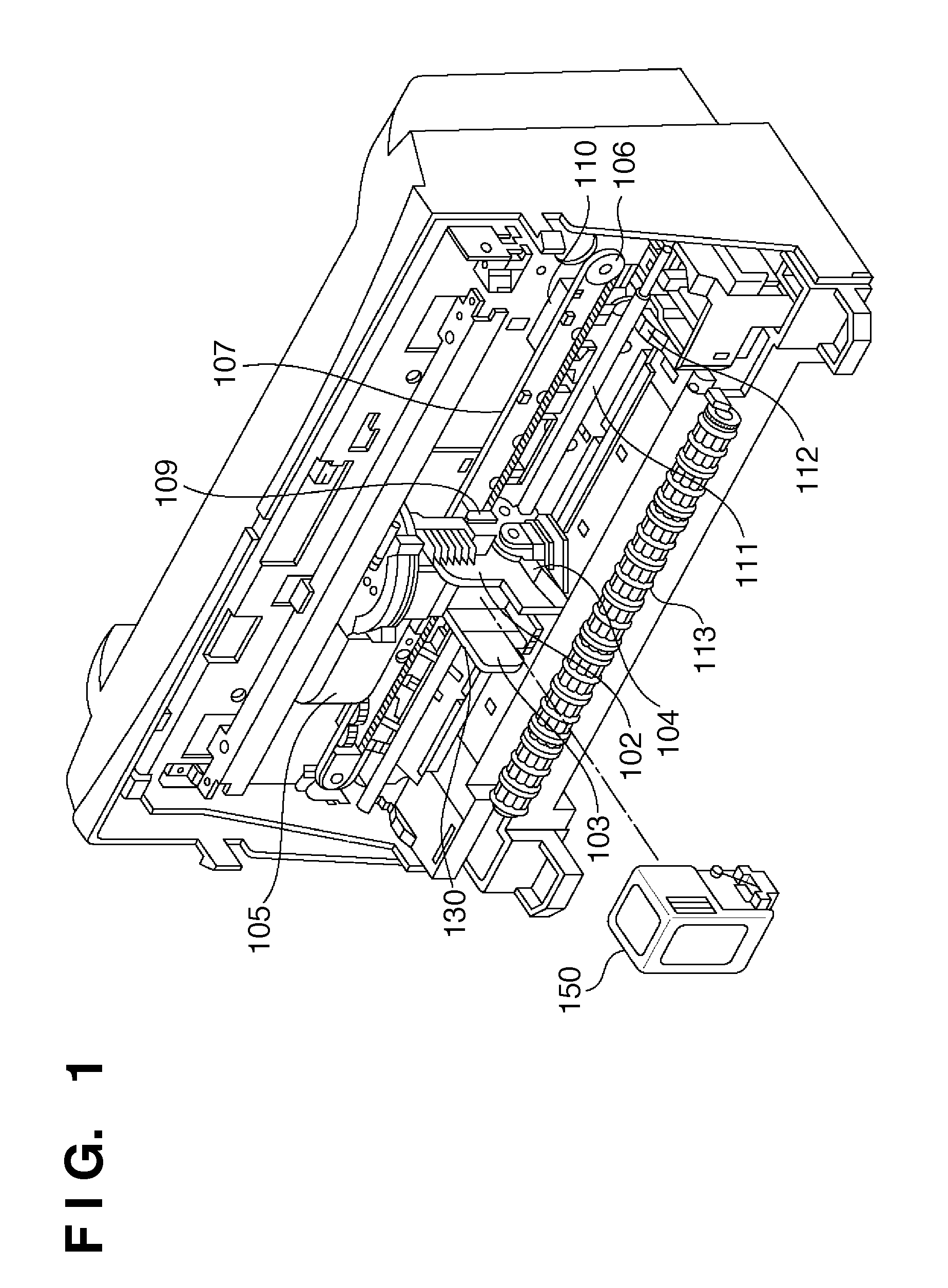
[0058]FIG. 1 is an external perspective view of a color ink jet printer according to a first embodiment. Incidentally, a front cover has been removed in FIG. 1 to reveal an interior of the apparatus.

[0059]In FIG. 1, reference numeral 150 denotes a replaceable ink jet cartridge and 102 refers to a carriage unit which detachably holds the ink jet cartridge. Reference numeral 103 denotes a holder used to secure the ink jet cartridge 150 to the carriage unit 102. A cartridge lock lever 104, when operated after the ink jet cartridge 150 is mounted in the carriage unit 102, brings the ink jet cartridge 150 into press contact with the carriage unit 102. Consequently, the ink jet cartridge 150 is positioned and an electrical contact installed on the side of the carriage unit 102 to transmit necessary signals is brought into c...

second embodiment

[0144]A method for reducing the fixed component by deriving the average amount of conveyance has been described in the first embodiment. However, eccentricity of the conveying roller or the like can cause degradation of recorded images as shown in FIG. 7. Thus, in a second embodiment, description will be given of a method for controlling the conveying roller by detecting a variable component in each phase during one rotation of the conveying roller in addition to detection of the fixed component described in the first embodiment and deriving an adjustment value in each phase. Incidentally, equipment configuration and the like is the same as the first embodiment, and thus description thereof will be omitted.

[0145]

[0146]It is known, for example, that the variable component (B in FIG. 5) affects a recorded image formed by 4 p1 of ink droplets if its amplitude is larger than 30 μm. That part of the variable component which is attributable to roller deformation and roller flexure can be ...

third embodiment

[0165]As a method for acquiring the conveyance amount for each phase angle of a rotation of the conveyance roller other than the embodiments mentioned above, the following method can also be used.

[0166]FIG. 24A and FIG. 24B explain a method for acquiring a conveyance amount of a printing medium.

[0167]Moreover, because the nozzle-space distance and accuracy of the print head necessary for the method to acquire the conveyance amount of the present embodiment are regulated by the print head creation process, known values are used. In particular, the present method uses a nozzle-space distance to acquire an amount of misalignment of the conveyance amount.

[0168]First, as shown in FIG. 24A, by discharging ink from nozzle 1 and nozzle 9 of the nozzle array of the print head as the carriage scans, two straight lines are printed in the scanning direction. Moreover, the distance between the two straight lines formed on the printing medium is the same as the distance between nozzles 1 and 9.

[0...


PUM


Abstract

In order to provide technique which reduce the positional shift of recording in the conveyance direction of a printing medium, a printing apparatus comprises: a conveyance unit for conveying the printing medium by rotating a roller; a detection unit for detecting a conveyance amount of a printing medium conveyed by rotating the roller in less than one rotation; an acquisition unit for acquiring a conveyance amount of the printing medium corresponding to a predetermined rotation amount of the roller by detecting the conveyance amount a plurality of times; and a setting unit for setting a rotation amount of the roller when forming an image on the printing medium based on a conveyance amount of a printing medium corresponding to the acquired predetermined rotation amount of the roller.

Description

TECHNICAL FIELD[0001]The present invention relates to a technique for controlling image forming position of a printing apparatus. More particularly, it relates to control of a conveying roller which conveys a printing medium.BACKGROUND ART[0002]An image forming apparatus of an ink jet type records on a printing medium by discharging ink from a print head during reciprocating motion in a main scanning direction. It forms an image by repeated recording in the main scanning direction while conveying the printing medium in a sub-scanning direction by means of a conveying roller. Generally, when conveying a printing medium, such as paper, on a conveying roller and the like, there are variations in the amount of conveyance (feed rate) depending on the mounting condition of the conveying roller, type of printing medium, and the like. Thus, patent document 1 discloses a technique for determining a correction value for the amount of conveyance based on printing results of a plurality of test...

Claims


Application Information

Patent Timeline
Patent Type & Authority Applications(United States)
IPC IPC(8): B41J29/38
CPCB41J2/1752B41J2/17523B41J29/393B41J11/42B41J29/38B41J2/2135
Inventor UCHIDA, NAOKI
Owner CANON KK
Why Eureka
Try Eureka