Object Detecting System

a technology of object detection and parallax, applied in the field of object detection systems, can solve the problems of low reliability of parallax, unnecessary braking is performed automatically, and much processing time is taken to calculate the reliability of parallax in this method and system, so as to improve the reliability of object detection and reduce the occurrence of mismatches

Active Publication Date: 2009-09-24
SUBARU CORP
View PDF5 Cites 36 Cited by
  • Summary
  • Abstract
  • Description
  • Claims
  • Application Information

AI Technical Summary

Benefits of technology

[0017]The present invention has been made in view of these circumstances, and an object of the invention is to provide an object detecting system that can accurately distinguish an object erroneously detected by mismatching, from objects detected by stereo matching.

Problems solved by technology

For example, if such erroneous object detection occurs in an object detecting system mounted in the vehicle so as to follow a preceding vehicle, particularly when another object is erroneously detected at a position closer than the preceding vehicle, information about the erroneous detection is transmitted to a preceding-vehicle follow-up system in an ECU (Electric Control Unit) of the vehicle, and as a result, unnecessary braking is performed automatically.
Unfortunately, much processing time is taken to calculate the reliability of the parallax in this method and system.
Therefore, even when the distance calculated on the basis of the parallax is correct, reliability thereof is low, and it is difficult to determine whether the obtained result is correct or wrong.

Method used


Image

  • Object Detecting System
  • Object Detecting System
  • Object Detecting System

Examples


Embodiment Construction

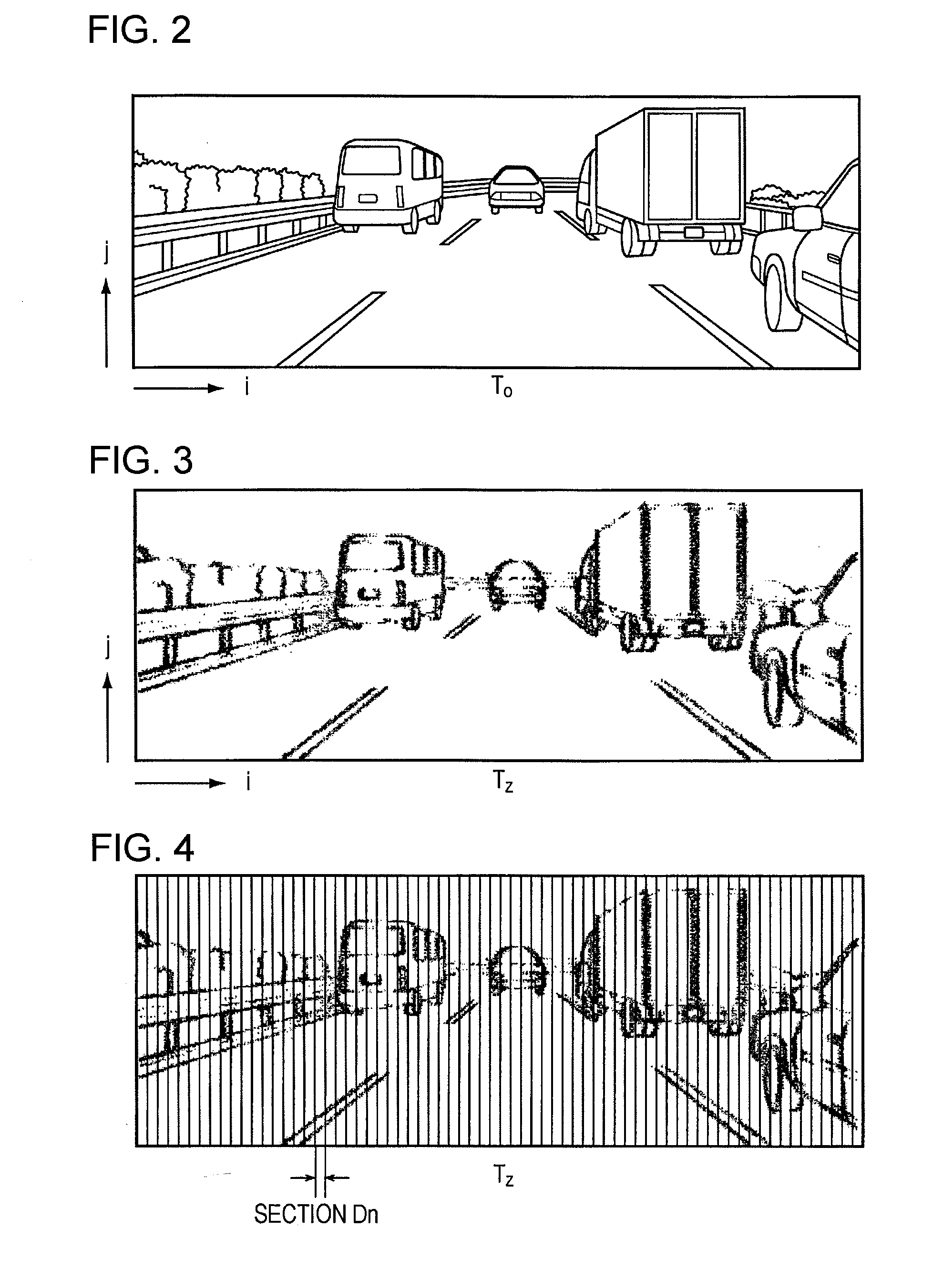
[0063]An object detecting system according to an embodiment of the present invention will be described below with reference to the drawings.

[0064]The following description will be given of a case in which an object detecting system is mounted in a vehicle so as to detect objects on or around the road. However, the object detecting system according to the present invention is also applicable to other cases.

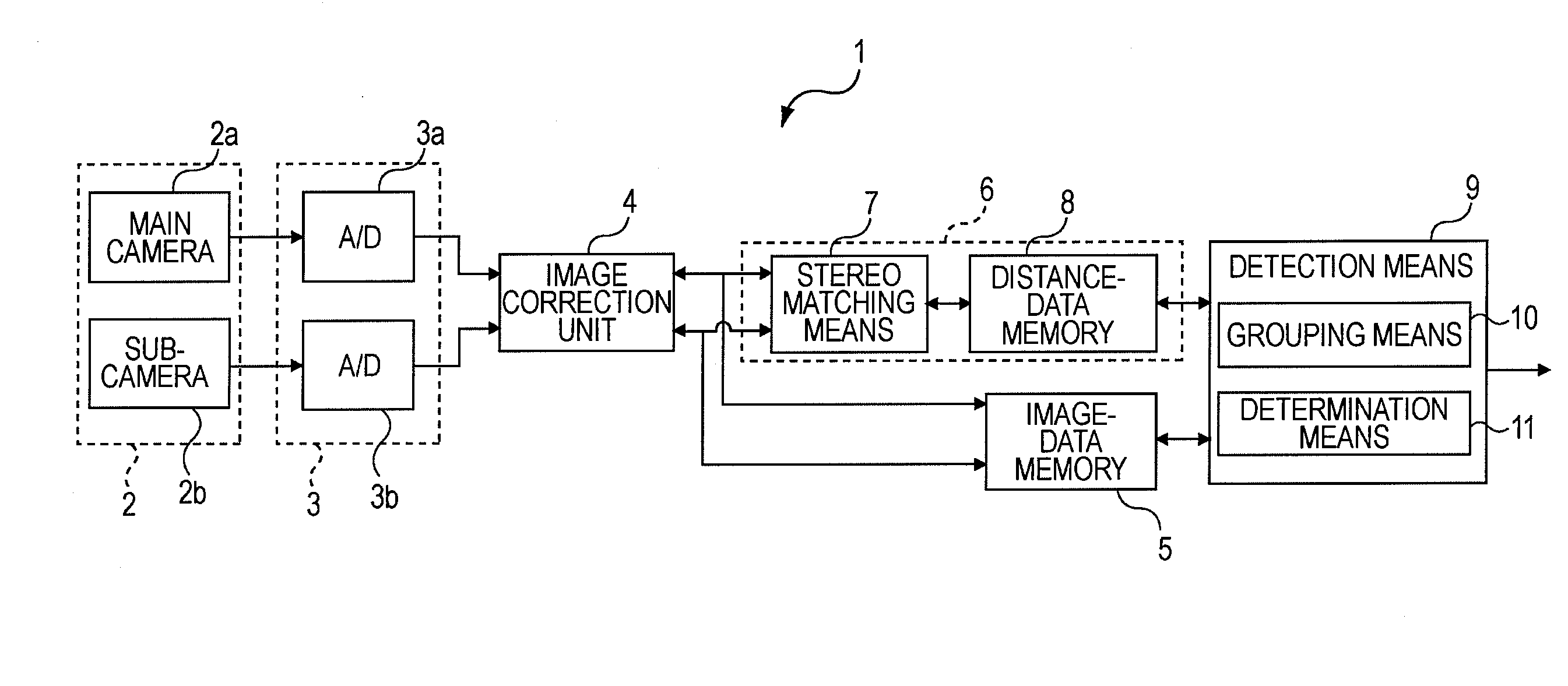
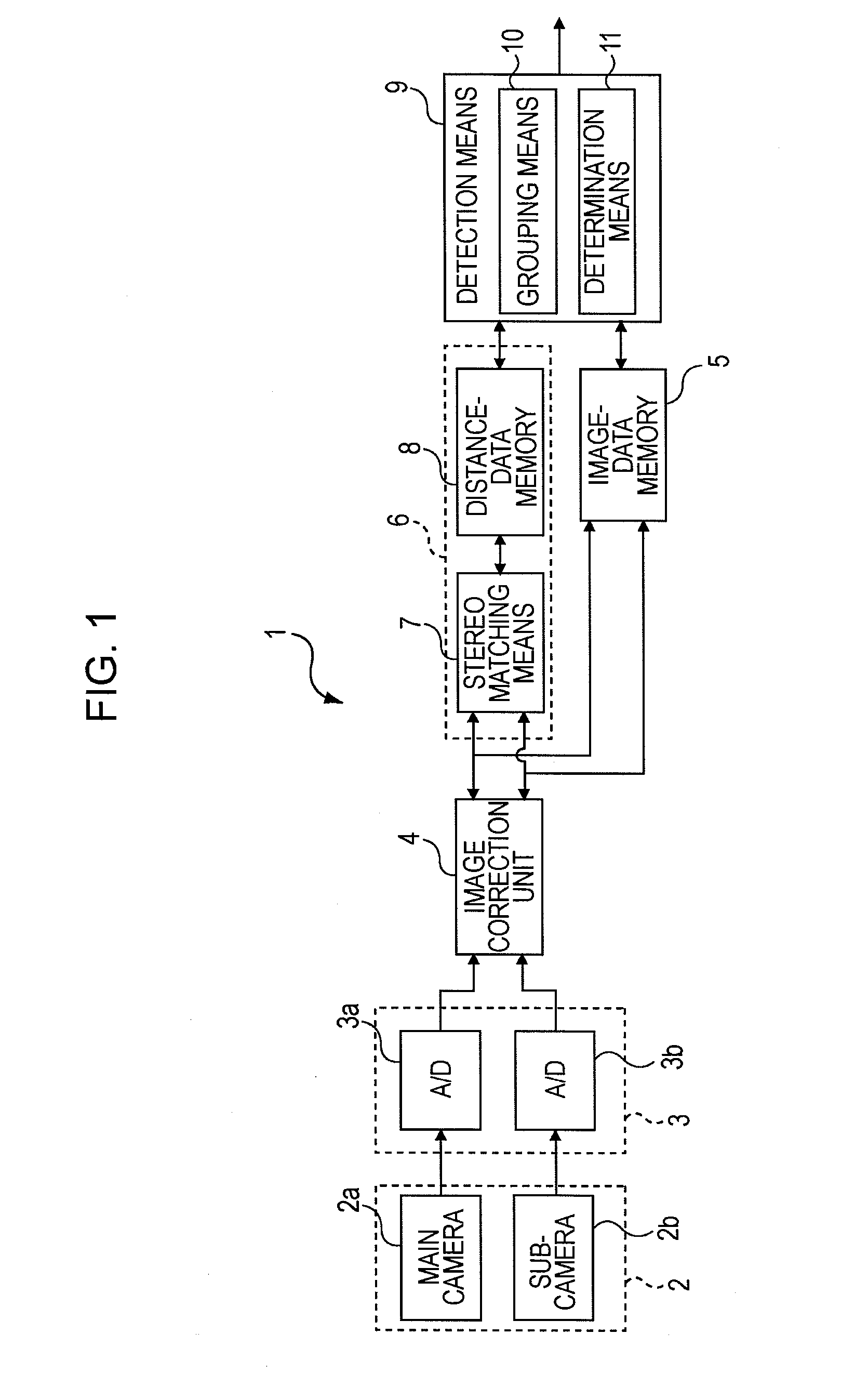
[0065]Referring to FIG. 1, an object detecting system 1 according to the embodiment includes a stereo-image taking means 2, a conversion means 3, an image processing means 6, and a detection means 9.

[0066]The structures from the stereo-image taking means 2 to a grouping means 10 in the detection means 9 have been described in detail in Japanese Unexamined Patent Application Publication Nos. 5-114099, 5-265547, 6-266828, 10-283461, 10-283477, and 2006-72495 filed earlier by the present applicant. Therefore, the structures will now be described briefly.

[0067]In this embodiment, the s...


PUM


Abstract

An object detecting system includes stereo-image taking means for taking images of an object and outputting the images as a reference image and a comparative image, stereo matching means for calculating parallaxes by stereo matching, and determination means for setting regions of objects in the reference image on the basis of the parallaxes grouped by grouping means, and performing stereo matching again for an area on the left side of a comparative pixel block specified on an epipolar line in the comparative image corresponding to a reference pixel block in a left end portion of each region. When a comparative pixel block that is different from the specified comparative pixel block and provides the local minimum SAD value less than or equal to a threshold value is detected, the determination means determines that the object in the region is mismatched.

Description

CROSS-REFERENCE TO RELATED APPLICATIONS[0001]The disclosure of Japanese Patent Application No. 2007-280470 filed on Oct. 29, 2007 including the specification, drawings and abstract is incorporated herein by reference in its entirety.BACKGROUND OF THE INVENTION[0002]1. Field of the Invention[0003]The present invention relates to object detecting systems, and more particularly, to an object detecting system that detects an object by stereo matching of a pair of images taken by stereo-image taking means.[0004]2. Description of the Related Art[0005]In general, in order to measure the distance to an object with a stereo camera, a pair of images are taken by a pair of right and left cameras that are mounted at the same height, and one of the taken images used for reference (hereinafter referred to as a reference image) is compared with the other image (hereinafter referred to as a comparative image). By comparison, a difference between positions of corresponding portions of the same objec...

Claims


Application Information

Patent Timeline
Patent Type & Authority Applications(United States)
IPC IPC(8): H04N13/02G06V10/10
CPCG01C11/06G06K9/20G06K9/00805G08G1/166G06K2209/40G06V20/58G06V10/10G06V2201/12
Inventor SAITO, TORU
Owner SUBARU CORP
Why Eureka
Try Eureka