Color belt fuser warm-up time minimization

a fuser and color belt technology, applied in the field of image forming equipment, can solve the problems of excessive heating power, heater element cracking, and amount of warm-up time required before the first print, and achieve the effect of quick warm-up of the fuser belt and increased heater power

Active Publication Date: 2009-09-24
LEXMARK INT INC
View PDF13 Cites 29 Cited by
  • Summary
  • Abstract
  • Description
  • Claims
  • Application Information

AI Technical Summary

Benefits of technology

[0008]Accordingly, it is an advantage of the present invention to provide an image forming apparatus such as a color electrophotographic (EP) printer which includes a belt fuser assembly that quickly warms up the fusing belt before allowing a first sheet of print media to run through the fuser assembly, in which a warm-up cycle includes: (1) a preheat mode, (2) a first portion of a belt temperature warm-up mode, (3) a second portion of the belt temperature warm-up mode, and (4) a tight belt temperature control mode.
[0009]It is another advantage of the present invention to provide a belt fuser assembly for a color electrophotographic (EP) printer that has a preheat mode which operates the fuser's heater at less than full power, and also prevents the fuser belt from rotating; a first portion of a belt temperature warm-up mode, in which the heater operates at full power, and the fuser belt begins rotating, but not at its full speed; a second portion of the belt temperature warm-up mode, in which the heater operates at less than full power (according to a temperature setpoint algorithm), and the fuser belt begins rotating at its full speed; and a tight belt temperature control mode, in which the fuser belt begins running at its “printing speed” if a print job is “ready,” while the belt temperature is controlled rather tightly to remain within its proper fusing temperature tolerance.
[0010]Additional advantages and other novel features of the invention will be set forth in part in the description that follows and in part will become apparent to those skilled in the art upon examination of the following or may be learned with the practice of the invention.
[0011]To achieve the foregoing and other advantages, and in accordance with one aspect of the present invention, a belt fuser assembly for an electrophotographic printer is provided, which comprises: (a) an endless fuser belt that rotates; (b) a heater for heating the fuser belt; (c) a backup member that engages the fuser belt and defines a fusing nip with the fuser belt; (d) a controller that provides a first signal for energizing the heater, and provides a second signal for rotating the fuser belt; (e) wherein the controller is configured to warm up the fuser belt before allowing the fuser assembly to perform a printing function, using the following routines: (i) a preheat mode; (ii) a first portion of a belt temperature warm-up mode; (iii) a second portion of the belt temperature warm-up mode; and (iv) a tight belt temperature control mode; (f) wherein during the preheat mode, the first signal energizes the heater such that the heater operates at less than full power, and the second signal prevents the fuser belt from rotating; (g) wherein during the first portion of the belt temperature warm-up mode, the first signal energizes the heater such that the heater operates at full power, and the second signal rotates the fuser belt at a first rotational speed; and (h) wherein during the second portion of the belt temperature warm-up mode, the first signal energizes the heater such that the heater operates at less than full power, and the second signal rotates the fuser belt at a second rotational speed that is greater than the first rotational speed.
[0012]In accordance with another aspect of the present invention, a belt fuser assembly for an electrophotographic printer is provided, which comprises: (a) an endless fuser belt that rotates; (b) a heater for heating the fuser belt; (c) a backup member that engages the fuser belt and defines a fusing nip with the fuser belt; (d) a controller that provides a first signal for energizing the heater, and provides a second signal for rotating the fuser belt; (e) a temperature sensor that is located proximal to the heater; (f) wherein the controller is configured to warm up the fuser belt before allowing the fuser assembly to perform a printing function, using the following routines: (i) a preheat mode; (ii) a belt temperature warm-up mode; and (iii) a tight belt temperature control mode; (g) wherein during the preheat mode, the first signal energizes the heater such that the heater operates at less than full power, in which the first signal operates using a first predetermined temperature setpoint value; (h) wherein during the belt temperature warm-up mode, the first signal continues to energize the heater as desired by the controller, in which the first signal operates using a second predetermined temperature setpoint value, wherein the second predetermined temperature setpoint value is greater than the first predetermined temperature setpoint value; and (i) wherein during the tight belt temperature control mode, the first signal continues to energize the heater as desired by the controller, in which the first signal operates using a third predetermined temperature setpoint value, wherein the third predetermined temperature setpoint value is less than the second predetermined temperature setpoint value.
[0013]In accordance with yet another aspect of the present invention, a belt fuser assembly for an electrophotographic printer is provided, which comprises: (a) an endless fuser belt that rotates; (b) a heater for heating the fuser belt; (c) a backup member that engages the fuser belt and defines a fusing nip with the fuser belt; (d) a controller that provides a first signal for energizing the heater, and provides a second signal for rotating the fuser belt; (e) a temperature sensor that is located proximal to the heater; (f) wherein the controller is configured to warm up the fuser belt before allowing the fuser assembly to perform a printing function, using the following routines: (i) check for a warm start mode by examining a temperature of the heater; (ii) if in a cold start mode: (A) set a heater power magnitude to less than full power; (B) monitor the heater temperature until it reaches a first value; and (C) after reaching the first value, switch to the warm start mode; and (iii) if in warm start mode: (A) turn on a motor for the fuser belt at about half speed; (B) increase the heater power to full power; (C) monitor the heater temperature until it reaches a second value; (D) after reaching the second value, switch fuser belt to full speed; (E) control the heater power at less than full power; (F) determine a time interval for operating in low power heating mode; (G) monitor elapsed time until it reaches the time interval; and (H) if print job is ready, control heater power to its printing value.

Problems solved by technology

Two of the most important issues when using a belt fuser for a color laser printer are the possibility of the heater element cracking and also the amount of the warm-up time required before the first print can be made.
However, excessive heating power can crack the heating element.
Unfortunately by limiting the temperature ramp-up rate, this also increases the fuser's warm-up time.

Method used


Image

  • Color belt fuser warm-up time minimization
  • Color belt fuser warm-up time minimization
  • Color belt fuser warm-up time minimization

Examples


Embodiment Construction

[0022]Reference will now be made in detail to the present preferred embodiment of the invention, an example of which is illustrated in the accompanying drawings, wherein like numerals indicate the same elements throughout the views. The exemplification(s) set out herein illustrate(s) at least one preferred embodiment of the invention, in at least one form, and such exemplification(s) (is)(are) not to be construed as limiting the scope of the invention in any manner.

[0023]The terms “first” and “second” preceding an element name, e.g., first signal, second signal, etc., or first rotational speed, second rotational speed, etc. are used for identification purposes to distinguish between similar or related elements, results or concepts, and are not intended to necessarily imply order, nor are the terms “first” and “second” intended to preclude the inclusion of additional similar or related elements, results or concepts, unless otherwise indicated.

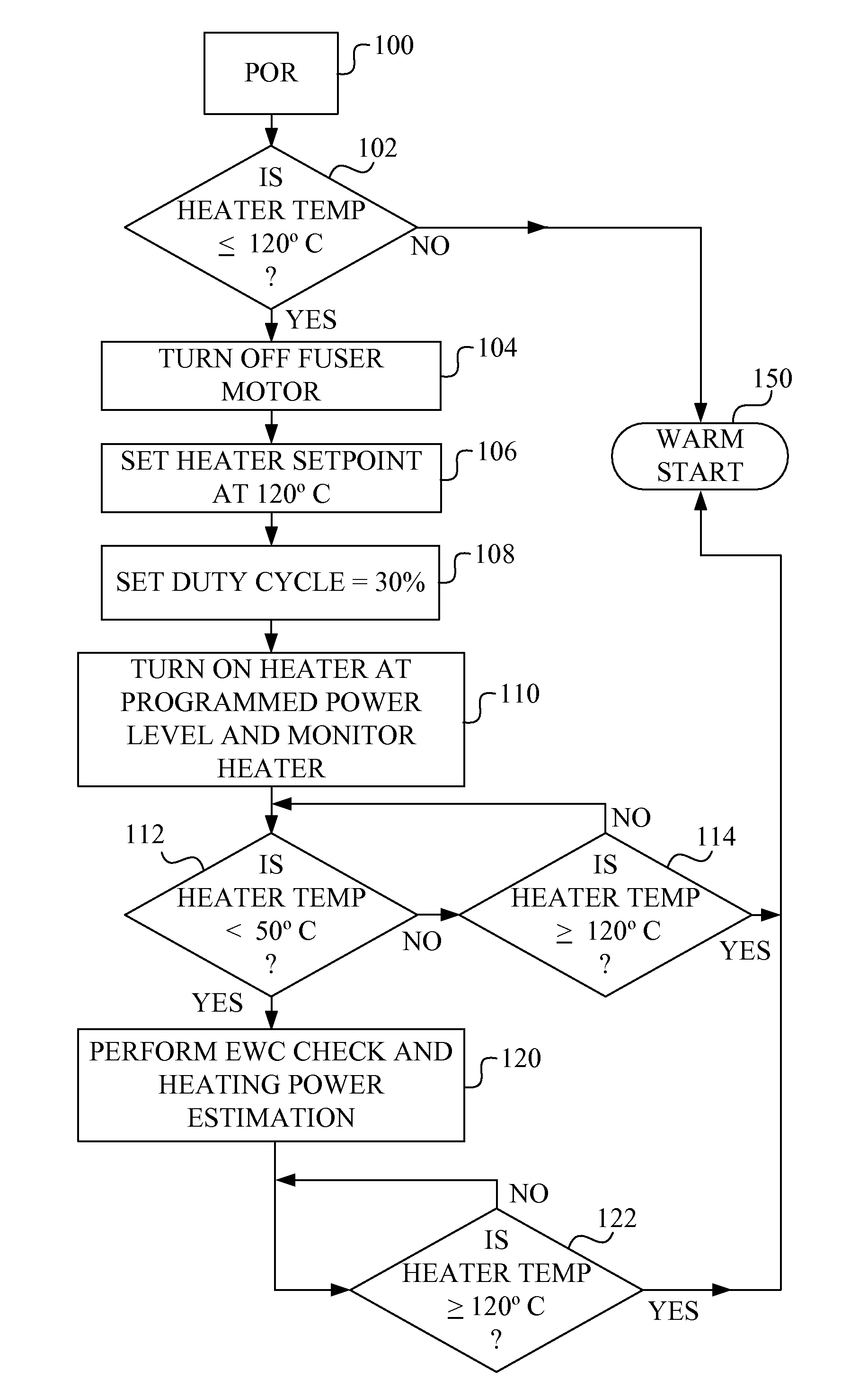
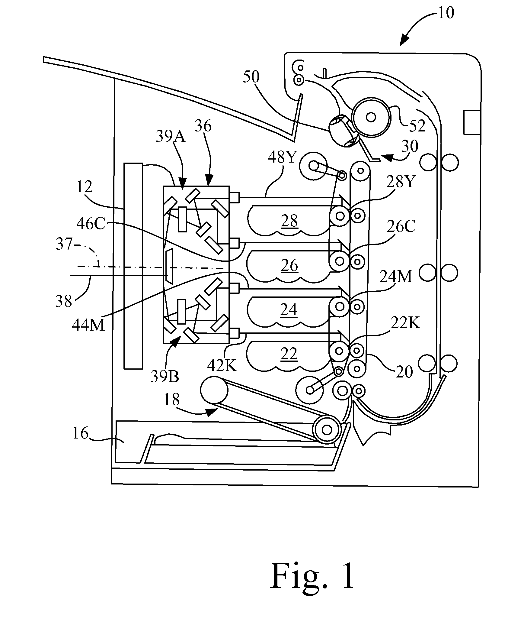
[0024]Referring now to the drawings, FIG....


PUM


Abstract

A belt fuser assembly for a color EP printer that quickly warms up the fusing belt before allowing a first sheet of print media to run through the printing stations at the fuser assembly. The warm-up cycle includes: (1) a preheat mode, (2) a first portion of a belt temperature warm-up mode, (3) a second portion of the belt temperature warm-up mode, and (4) a tight belt temperature control mode. The preheat mode operates the fuser's heater at less than full power, and prevents the fuser belt from rotating. The first portion of the belt temperature warm-up mode operates the heater at full power, and the fuser belt begins rotating, but not at its full speed. The second portion of the belt temperature warm-up mode operates the heater at less than full power, and the fuser belt begins rotating at its full speed.

Description

BACKGROUND OF THE INVENTION[0001]1. Field of the Invention[0002]The present invention relates generally to image forming equipment and is particularly directed to electrophotographic (EP) printers of the type which use fusers to fix toner to print media, such as paper sheets. The invention is specifically disclosed as a belt fuser assembly for a color EP printer that quickly warms up the fusing belt before allowing a first sheet of print media to run through the fuser assembly. The warm-up cycle includes: (1) a preheat mode, (2) a first portion of a belt temperature warm-up mode, (3) a second portion of the belt temperature warm-up mode, and (4) a tight belt temperature control mode. Certain parameters are sensed or calculated before moving from one mode to the next.[0003]In one embodiment, the preheat mode operates the fuser's heater at less than full power, and also prevents the fuser belt from rotating. During the first portion of the belt temperature warm-up mode, the heater ope...

Claims


Application Information

Patent Timeline
Patent Type & Authority Applications(United States)
IPC IPC(8): G03G15/20
CPCG03G15/2039G03G2215/2035
Inventor CAO, JICHANGGILMORE, JAMES DOUGLASGOGATE, HRISHIKESH PRAMODMCINTIRE, WESLEY DAVIDMURPHY, CALVIN DALESWITZER, THAD CARLTON
Owner LEXMARK INT INC
Why Eureka
Try Eureka