Air enclosure without heat resistant material and manufacturing of same

Inactive Publication Date: 2009-09-24
LIAO CHIEH HUA
View PDF4 Cites 14 Cited by
  • Summary
  • Abstract
  • Description
  • Claims
  • Application Information

AI Technical Summary

Benefits of technology

[0007]To improve an air inlet of an air enclosure and its manufacturing process, decreasing the labor and the material costs consumed by spreading a heat resistant material and in the meantime, allowing the air inlet to be opened effectively so as to enable the air filling to be continuous to save the air filling time, the present invention is proposed.
[0021]Where it is not necessary to spread a heat resistant material in advance according to the present invention, the two sheets of inner film are stacked together directly and the heat resistant pad is used to place in between the two inner films to form the air inlet by means of hot sealing thereby shortening the manufacturing process effectively and reducing the labor and the material costs substantially. In addition, when the two sheets of outer film are pulled apart, the air inlets formed by the inner films are opened automatically, air is filled into the plurality of air cylinders via the air inlets; it is unnecessary to position each air inlet while being filled with air, thus reducing the air filling time. Each air cylinder is independent and the cushioning effect is not influenced even if some air cylinders are broken. The air in the air cylinder compresses the inner films to cover the air inlet to shield the air cylinder creating an air lock.

Problems solved by technology

However, foam can be attached closely to a surface of the article, but mere impact protection is sub-optimal; the article is still frequently struck and damaged.
Moreover, foam is difficult to deal with; it is accompanied by environmental protection issues.
The Styrofoam may prevent an article from being damaged by shaking, but a bouffant volume of Styrofoam occupies a large volume, does not decompose easy, and will release poisonous gas after incineration, causing serious environmental pollution.
Thus foam and Styrofoam cause environmental protection problems; Styrofoam is not an ideal cushioning material in the current culture of heightened environmental consciousness.
Hence, not only the material cost is increased but the process of spreading the heat resistant material is time and labor wasting; this prevents the effective reduction of the production cost of an air enclosure.

Method used


Image

  • Air enclosure without heat resistant material and manufacturing of same
  • Air enclosure without heat resistant material and manufacturing of same
  • Air enclosure without heat resistant material and manufacturing of same

Examples


Embodiment Construction

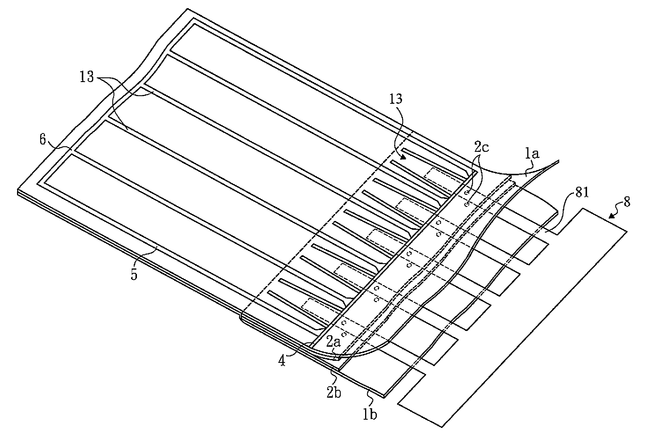
[0036]Please refer to FIGS. 3, 4, 5, 6A, 6B, 7A and 7B. FIG. 3 is a perspective view, showing an air enclosure of a first embodiment according to the present invention after being filled with air. FIG. 4 is a schematic view, showing an air enclosure of the first embodiment according to the present invention while being manufactured by inserting a heat resistant pad. FIG. 5 is a plane view, showing an air enclosure of the first embodiment according to the present invention after being filled with air. FIG. 6A is a schematic view, showing a heat resistant pad of the first embodiment according to the present invention while being manufactured. FIG. 6B is a plane view, showing an air enclosure of the first embodiment according to the present invention before being filled with air. FIGS. 7A and 7B are cross sectional views, showing an air enclosure of the first embodiment while being manufactured by inserting a heat resistant pad.

[0037]An air enclosure without a heat resistant material i...


PUM

PropertyMeasurementUnit
Electrical resistanceaaaaaaaaaa
Heataaaaaaaaaa

Abstract

An air enclosure without a heat resistant material is formed by stacking two outer films and two inner films, allowing the two inner films to be lain in between the two outer films, placing a heat resistant pad between the two inner films, adhering the two outer films and the two inner films to each other to form at least one air inlet between the two inner films and at least one air cylinder between the two outer films, and thereafter, taking out the heat resistant pad, and filling air into the air cylinder via the air inlet to cause the air cylinder to be filled with air and expanded, where the air in the air cylinder compresses the two inner films to cover the air inlet to shield the air cylinder.

Description

CROSS-REFERENCES TO RELATED APPLICATIONS[0001]This non-provisional application claims priority under 35 U.S.C. §119(a) on Patent Application No(s). 97110269 filed in Taiwan, R.O.C. on Mar. 21, 2008, the entire contents of which are hereby incorporated by reference.FIELD OF THE INVENTION[0002]The present invention relates to an air enclosure and a method for manufacturing it, and more particularly to an air enclosure without a heat resistant material and a method for manufacturing it.BACKGROUND[0003]Generally, when an article is packed, a soft material such as foam or Styrofoam is used to provide the article with a cushioning protection. However, foam can be attached closely to a surface of the article, but mere impact protection is sub-optimal; the article is still frequently struck and damaged. Moreover, foam is difficult to deal with; it is accompanied by environmental protection issues. The Styrofoam may prevent an article from being damaged by shaking, but a bouffant volume of S...

Claims


Application Information

Patent Timeline
IPC IPC(8): B32B1/08B29C65/00
CPCB29C65/02B29C66/004B29C66/1122B29C66/24B29C66/43B29L2022/02Y10T428/13B32B27/08B65D81/052B29L2031/7138B29C65/00B29C66/244B32B3/04B32B3/28B32B3/30B32B2250/44B32B2307/31B32B2553/00B32B7/05
Inventor LIAO, CHIEH HUALIAO, YAW SHINLIAO, YAO CHUAN
Owner LIAO CHIEH HUA
Why Eureka
Try Eureka