Bloused Stent-Graft and Fenestration Method

a stent-graft and fenestration technology, applied in the field of intravascular devices and methods, can solve the problems of time-consuming and high cost of custom fabrication of main stent-grafts, and achieve the effect of facilitating the self-alignment of the puncture devi

Active Publication Date: 2009-09-24
MEDTRONIC VASCULAR INC
View PDF13 Cites 67 Cited by
  • Summary
  • Abstract
  • Description
  • Claims
  • Application Information

AI Technical Summary

Benefits of technology

[0012]As set forth above, by forming the bloused section with loose graft cloth, the pocket is self-aligned with the branch vessel as the loose graft cloth is forced into the branch vessel. The pocket, in turn, f...

Problems solved by technology

However, custom fabrication of main stent-grafts is relatively expensive and time consuming.
However, due to difficulties in accurately placement of...

Method used


Image

  • Bloused Stent-Graft and Fenestration Method
  • Bloused Stent-Graft and Fenestration Method
  • Bloused Stent-Graft and Fenestration Method

Examples


Embodiment Construction

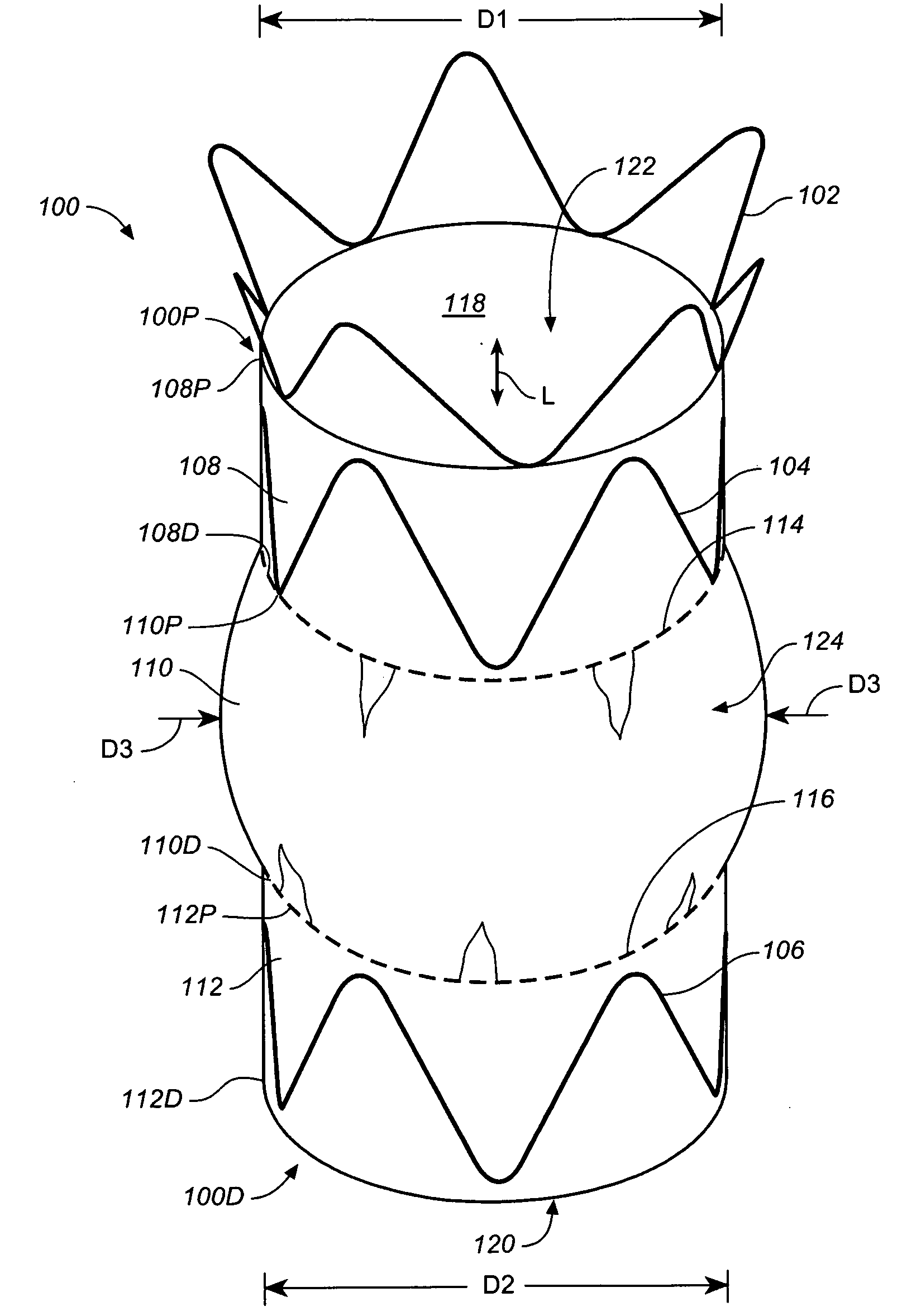
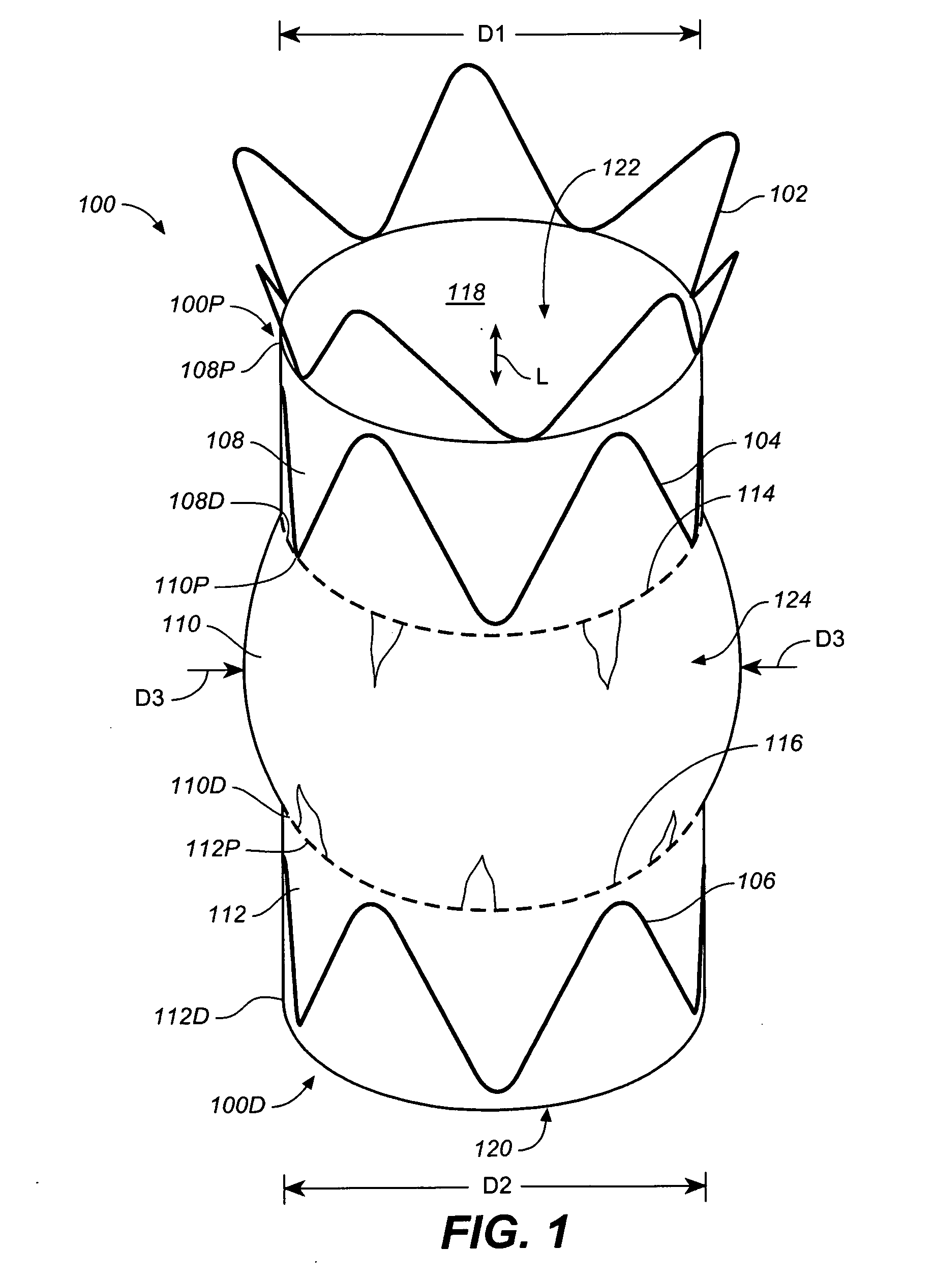
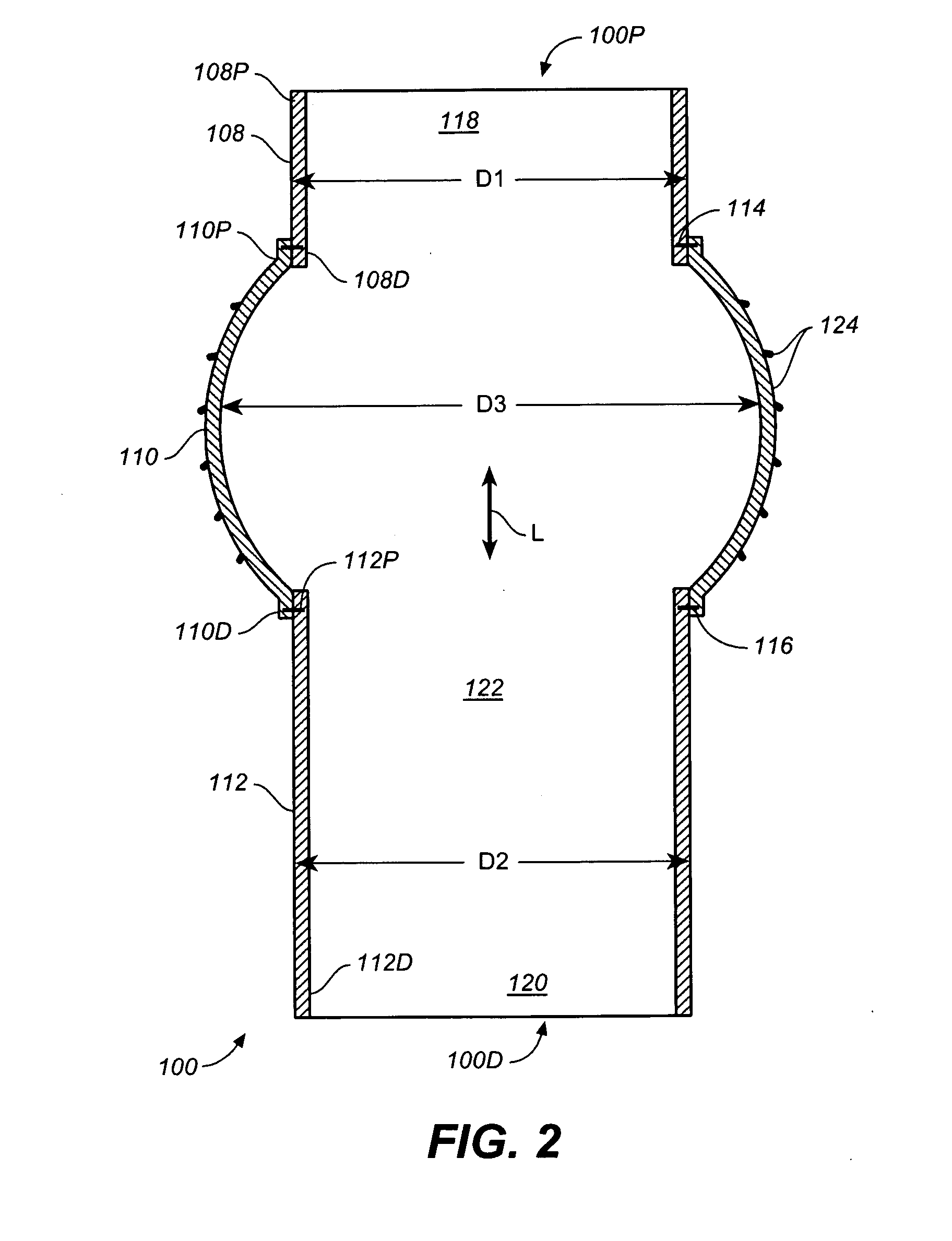
[0022]Referring to FIG. 3, a method includes deploying a bloused stent-graft 100 into a main vessel 302 such that a bloused section 110 of bloused stent-graft 100 covers a branch vessel 306 emanating from main vessel 302. Bloused section 110 includes loose graft cloth.

[0023]Referring now to FIGS. 3 and 4 together, a pressure differential between main vessel 302 and branch vessel 306 causes bloused section 110 to be forced into an ostium 310 of branch vessel 306 creating a pocket 316 precisely aligned with branch vessel 306.

[0024]Referring now to FIG. 5, a distal tip 504 of a steerable puncture device 502 is located in pocket 316 and thus precisely aligned with branch vessel 306. An outward force is applied to steerable puncture device 502 to cause distal tip 504 of steerable puncture device 502 to fenestrate bloused section 110 thus creating a collateral opening 602 (FIG. 6) in bloused section 110 precisely aligned with branch vessel 306.

[0025]Referring now to FIG. 5A, a distal tip ...


PUM


Abstract

A method includes deploying a bloused stent-graft into a main vessel such that a bloused section of the bloused stent-graft covers a branch vessel emanating from the main vessel. The bloused section includes loose graft cloth. A pressure differential between the main vessel and the branch vessel causes the bloused section to be forced into an ostium of the branch vessel creating a pocket aligned with the branch vessel. A distal tip of a puncture device is located in the pocket and thus aligned with the branch vessel. An outward force is applied to the puncture device to cause the distal tip of the puncture device to fenestrate the bloused section thus creating a collateral opening in the bloused section precisely aligned with the branch vessel.

Description

BACKGROUND OF THE INVENTION[0001]1. Field of the Invention[0002]The present invention relates to an intra-vascular device and method. More particularly, the present invention relates to a device for treatment of intra-vascular diseases.[0003]2. Description of Related Art[0004]A conventional main (vessel) stent-graft typically includes a radially expandable reinforcement structure, formed from a plurality of annular stent rings, and a cylindrically shaped layer of graft material, sometimes called graft cloth, defining a lumen to which the stent rings are coupled. Main stent-grafts are well known for use in tubular shaped human vessels.[0005]To illustrate, endovascular aneurysmal exclusion is a method of using a main stent-graft to exclude pressurized fluid flow from the interior of an aneurysm, thereby reducing the risk of rupture of the aneurysm and the associated invasive surgical intervention.[0006]Main stent-grafts with custom side openings are sometimes fabricated to accommodate...

Claims


Application Information

Patent Timeline
IPC IPC(8): A61F2/82A61F2/06
CPCA61F2/07A61F2002/061A61F2230/0013A61F2220/005A61F2220/0075A61F2/89
Inventor BRUSZEWSKI, WALTER
Owner MEDTRONIC VASCULAR INC
Why Eureka
Try Eureka