
Method and Apparatus for Operating an Automated High Temperature Thermal Cutting System

a cutting system and high temperature technology, applied in welding apparatuses, manufacturing tools, instruments, etc., can solve the problems of inability to adequately operate an automated high temperature thermal cutting system, which is not familiar with the mechanics of the digital signal processor,

Active Publication Date: 2009-09-24
HYPERTHERM INC
View PDF13 Cites 47 Cited by
  • Summary
  • Abstract
  • Description
  • Claims
  • Application Information

AI Technical Summary

Benefits of technology

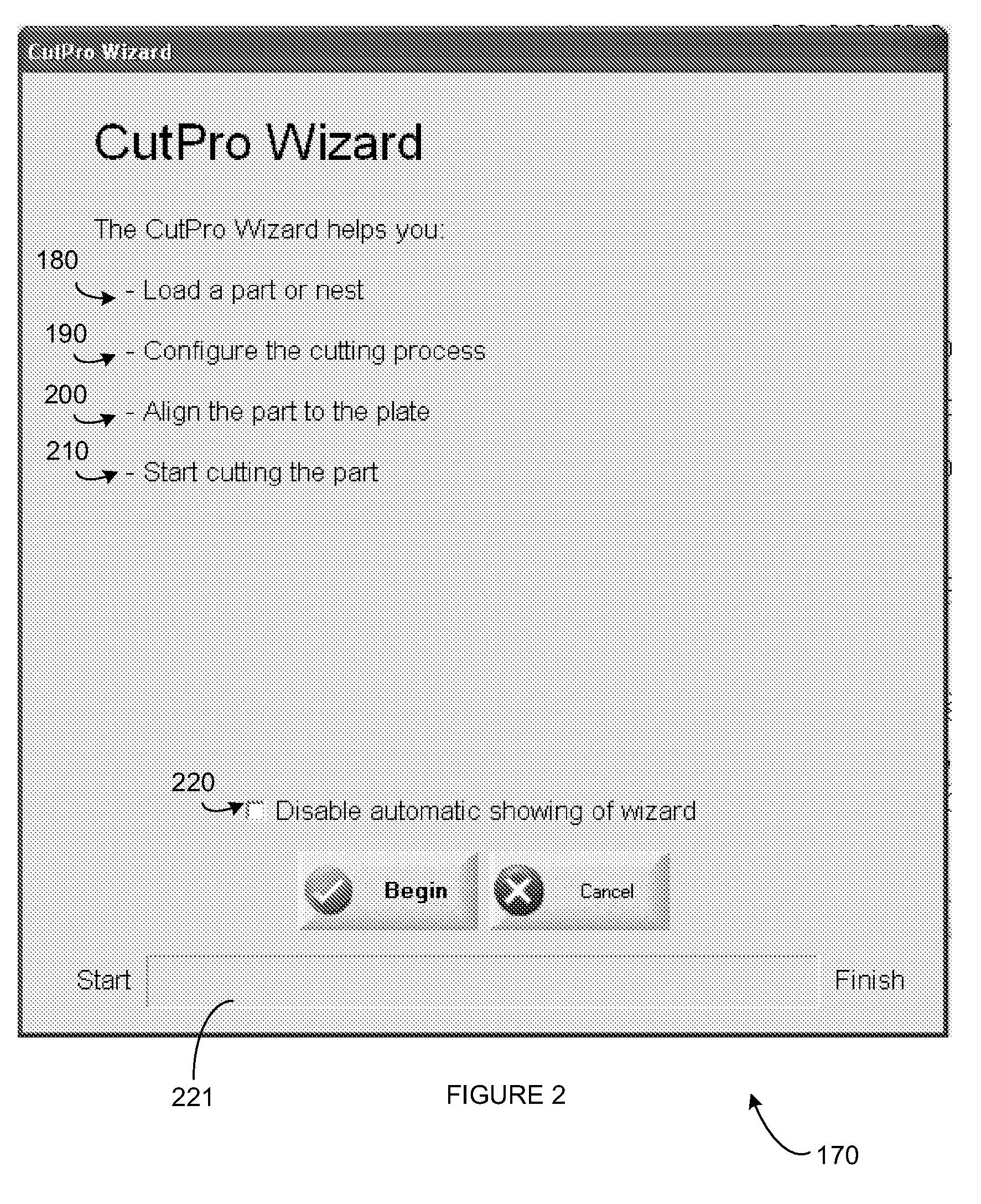
[0047]FIG. 14 shows an example of a user interface of a computer program system for reviewing operation settings for an automated high temperature thermal cutting system, according to an illustrative embodiment of the invention.
[0048]FIG. 15 shows an example of a user interface of a computer program system for reviewing operation settings for an automated high temperature thermal cuttin

Problems solved by technology

A novice user unfamiliar with the desired ranges / choices for operating parameters for different processes and unfamiliar with the mechanics of the digital signal processor would not be able to adequately operate an automated high temperature thermal cutting system.

Method used


Image

  • Method and Apparatus for Operating an Automated High Temperature Thermal Cutting System
  • Method and Apparatus for Operating an Automated High Temperature Thermal Cutting System
  • Method and Apparatus for Operating an Automated High Temperature Thermal Cutting System

Examples


Embodiment Construction

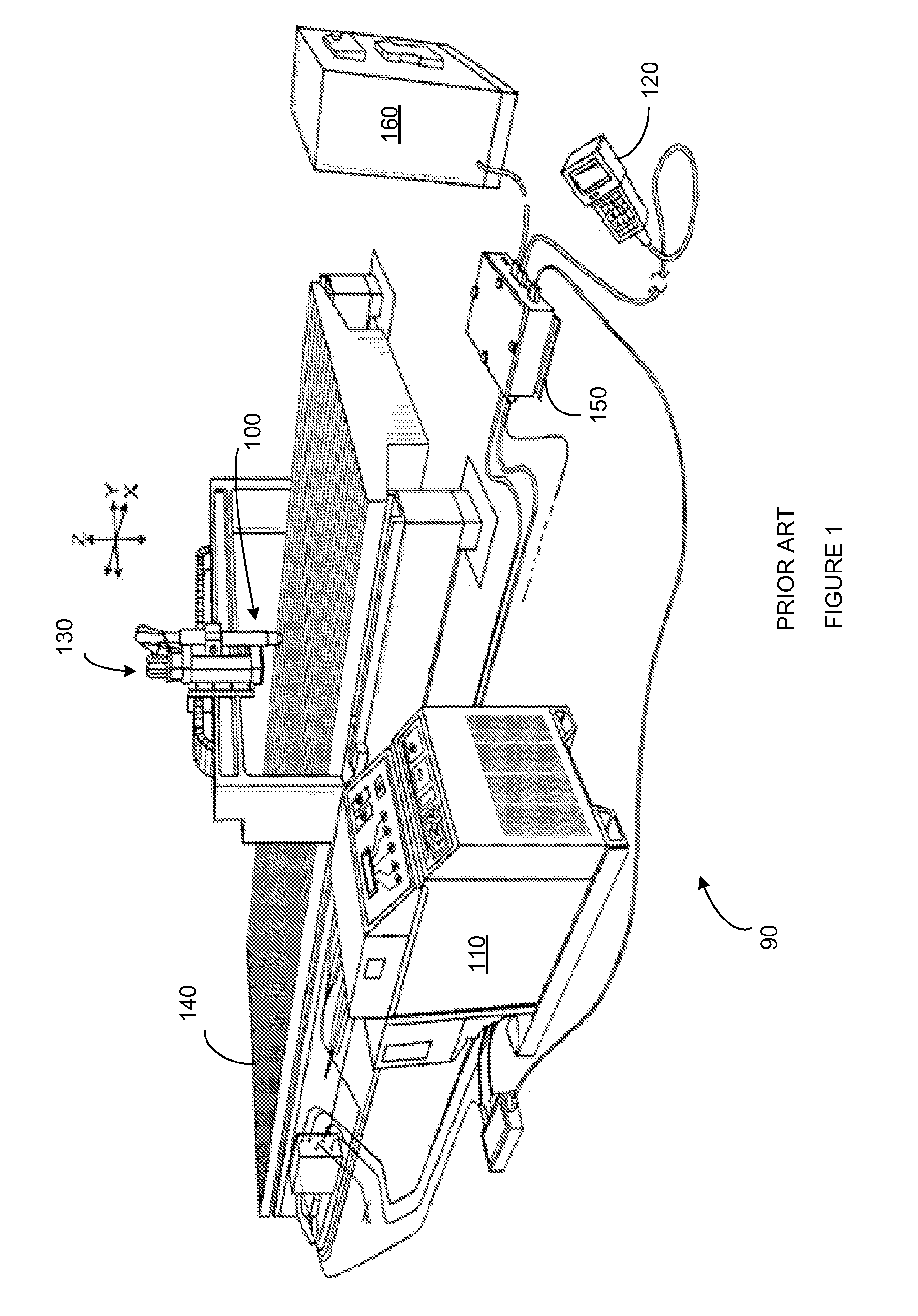
[0051]An automated (e.g., mechanized) high temperature thermal cutting and / or processing system can include a laser cutting system or a plasma arc torch system 90 (e.g., the plasma arc torch system as shown in FIG. 1). Automated high temperature thermal cutting systems can be complex and be extremely difficult for a novice user to operate effectively. A computer program system (CPS) (e.g., a computer readable product such as a computer and / or software program tangibly embodied in a machine-readable storage device, for example, in a CD ROM, USB hard drive, or hard drive of a digital signal processor 160 shown in FIG. 1) can be used to guide the user to configure operating parameters (e.g., cutting tool parameters) for the cutting system. A CPS can also be an apparatus such as a CNC (Computerized Numeric Controller) (or other Digital Signal Processor (DSP)), embodying the method of the invention to store data or to display the inputs or results of the invention. Various modules of the...


PUM

PropertyMeasurementUnit
Fractionaaaaaaaaaa
Temperatureaaaaaaaaaa
Thicknessaaaaaaaaaa

Abstract

A method for setting up a cutting table for an automated high temperature thermal cutting system can include providing a computer-readable product to, for example, a digital signal processor (e.g., CNC). The computer-readable product can include data for at least one part to be cut from a workpiece (e.g., a part program). A user can be prompted to select values from a menu of mandatory operating parameters (e.g., using a graphical user interface) for a shape of the part to be cut from the workpiece. Mandatory operating parameters can include at least one of an operating current, a gas flow, a thickness of the workpiece, or a material of the workpiece.

Description

CROSS-REFERENCE TO RELATED APPLICATION[0001]This application claims the benefit of and priority to U.S. Provisional Patent Application No. 61 / 039,077 filed on Mar. 24, 2008, which is owned by the assignee of the instant application and the disclosure of which is incorporated herein by reference in its entirety.FIELD OF THE INVENTION[0002]The invention relates generally to the cutting of workpieces. More specifically, the invention relates to methods and devices for operating automated cutting systems, such as high temperature thermal cutting systems.BACKGROUND OF THE INVENTION[0003]High temperature thermal cutting systems (e.g., plasma arc systems, laser cutting systems, etc.) can be used for cutting metallic materials. The high temperature thermal cutting systems can be automated for automatically cutting a metallic workpiece. FIG. 1 shows a known automated plasma arc system 90. The depicted plasma arc cutting system 90 includes a plasma arc torch 100, an associated power supply / ga...

Claims


Application Information

Patent Timeline
IPC IPC(8): G06F19/00B23K9/00
CPCB23K31/10
Inventor YOUNG, JR., ROGER E.BRAHAN, PETER V.
Owner HYPERTHERM INC
Learn More