
Electric shaver

a shaving device and electric technology, applied in the direction of metal working devices, etc., can solve the problems of difficulty in increasing the rockable range in reality, the width of the main body block, etc., and achieve the effect of widening the support arm

Active Publication Date: 2009-10-01
PANASONIC CORP
View PDF13 Cites 32 Cited by
  • Summary
  • Abstract
  • Description
  • Claims
  • Application Information

AI Technical Summary

Benefits of technology

[0010]In the present invention, it is preferable that a width of the support arm in the reciprocating direction of the inner blade is increased from its base end toward its tip end.

Problems solved by technology

Thus, in order to increase the rockable range of the head block, the width of the main body block needs to increase, and there is a problem in that it is difficult to increase the rockable range in the reality.

Method used


Image

  • Electric shaver
  • Electric shaver
  • Electric shaver

Examples


first embodiment

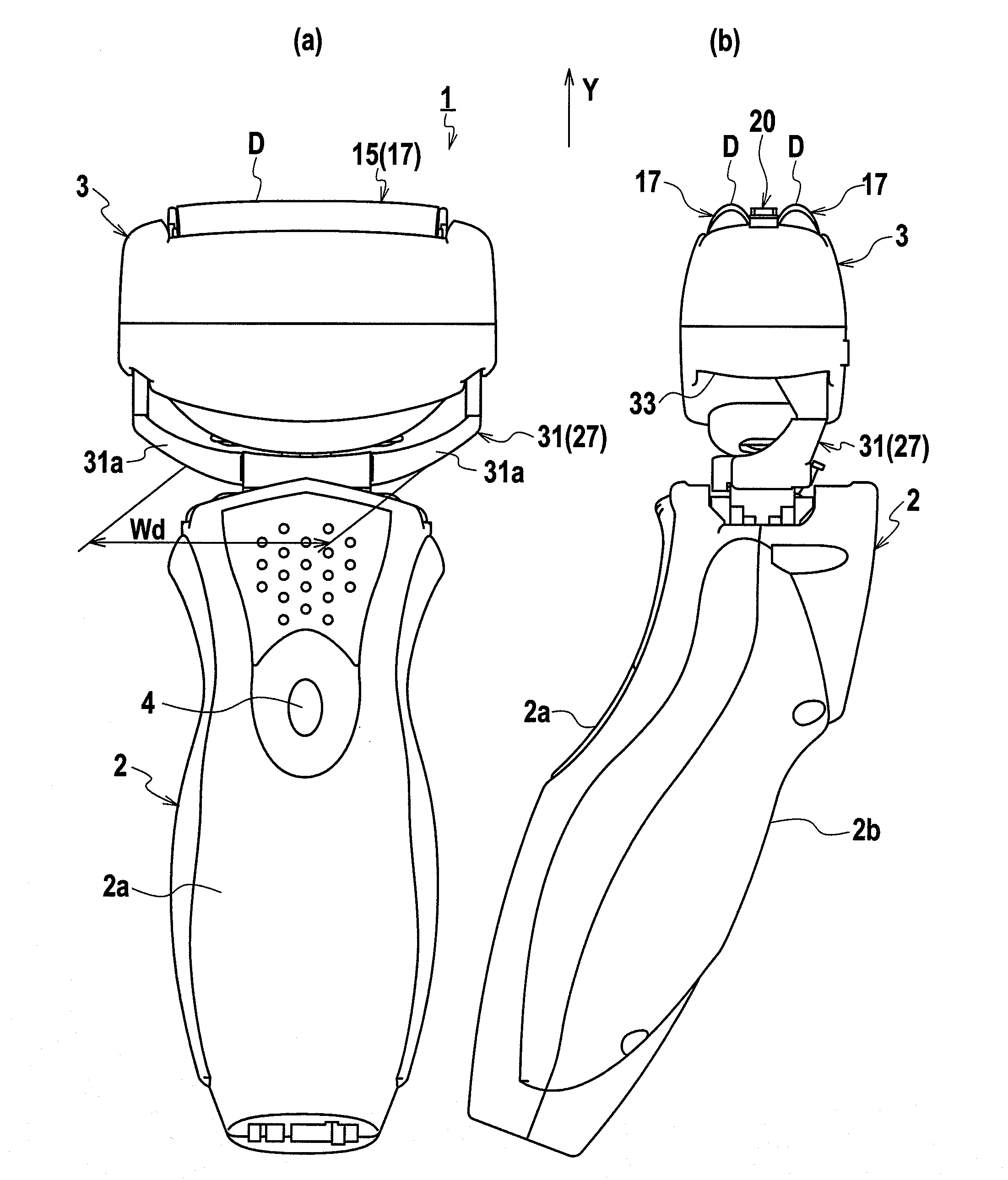
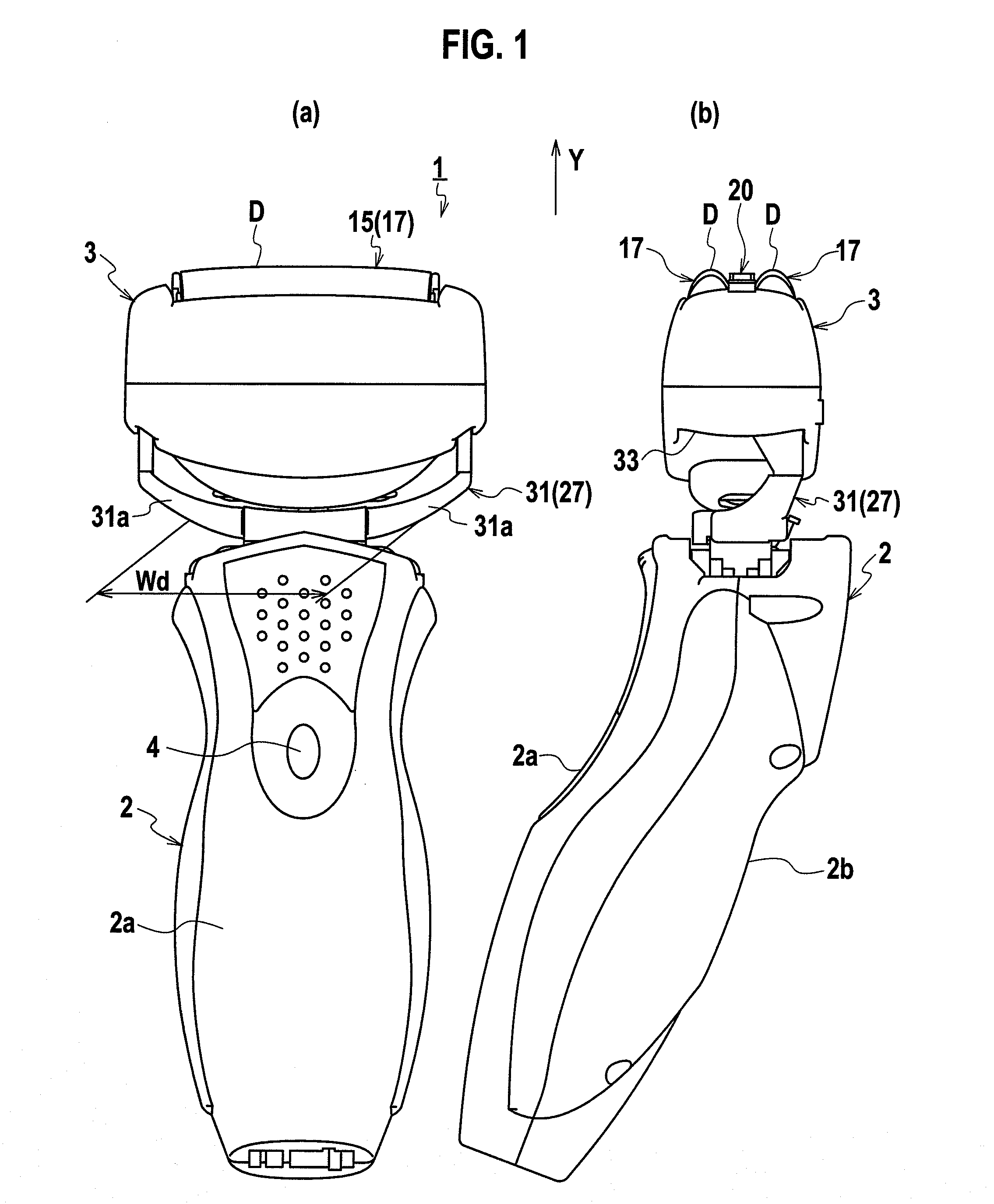
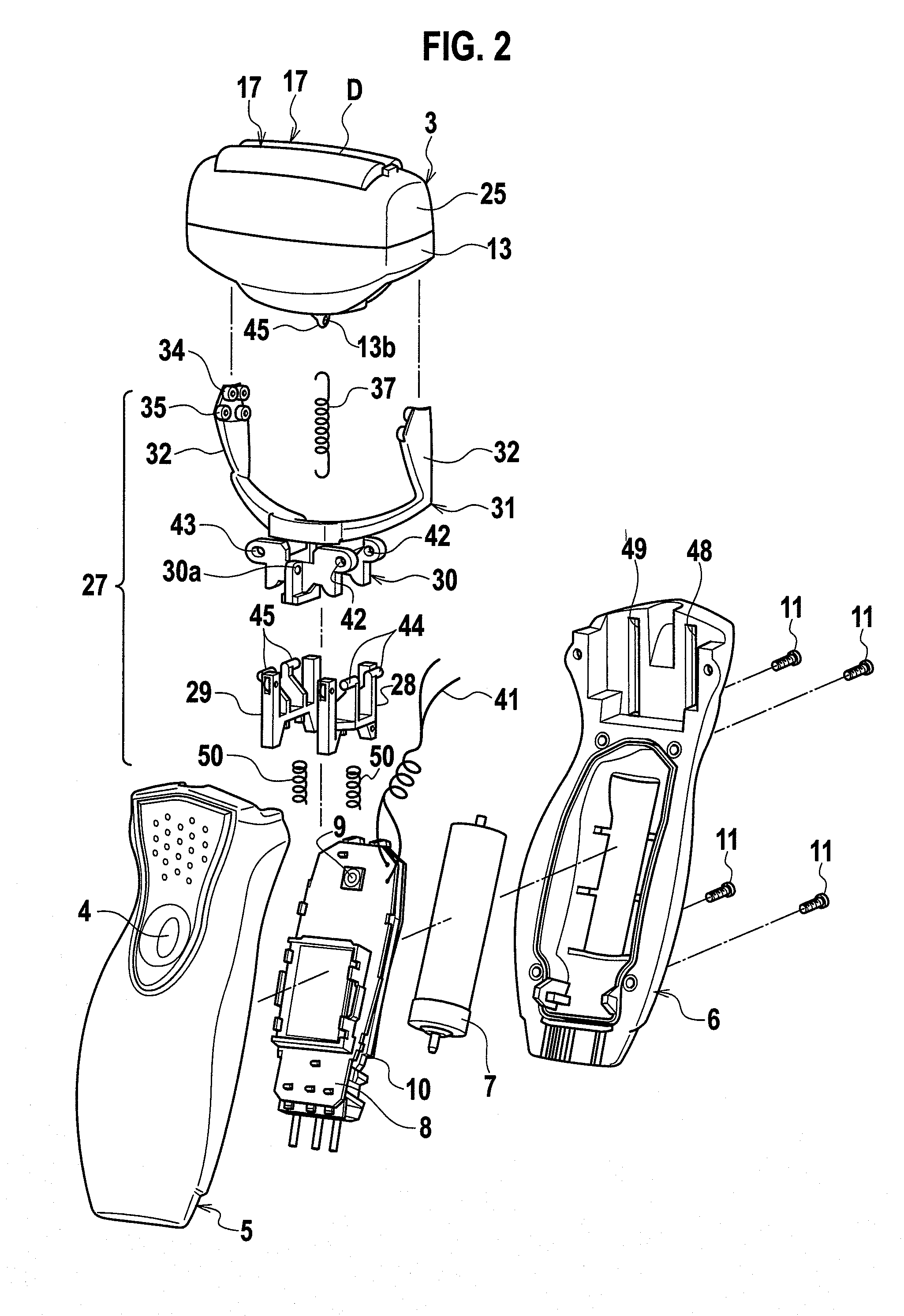
[0027]FIG. 1 are front and side views of an electric shaver according to the present embodiment, FIG. 2 is an exploded perspective view of the electric shaver, FIG. 3 is an exploded perspective view of a head portion of the electric shaver, FIG. 4 is an exploded perspective view of a support arm of the electric shaver, FIG. 5 are explanatory diagrams showing a variation of a support state of a blade head by the support arm, FIG. 6 is a front sectional view showing an internal structure of a connecting portion between the blade head and a grip portion, FIG. 7 is a side sectional view of the electric shaver, and FIG. 8 are explanatory diagrams showing a variation of a rocking state of the blade head.

[0028]In the following explanations, for the sake of convenience, FIG. 1(a) is defined as a front view, FIG. 1(b) is defined as a side view, the left side in FIG. 1(b) is defined as a front side and the right side in FIG. 1(b) is defined as a back side. Upper and lower sides are defined as...

second embodiment

[0072]FIG. 9 is an exploded perspective view of relevant parts of the support arm according to the present embodiment. FIG. 10 is a vertical sectional view of a connection between the blade head and the grip portion. The electric shaver according to the present embodiment has the same constituent elements as those of the electric shaver of the first embodiment. Therefore, the same constituent elements are designated with the same reference numerals, and redundant explanation will be omitted.

[0073]In the present embodiment, at least two arm divided bodies 31L and 31R are combined to constitute the arm portion 31 of the support arm 27.

[0074]According to the present embodiment, the freedom degree in a procedure for assembling the elements is enhanced, and it is possible to easier and more quickly assemble the support arm 27, engage the guide rollers 34 and 35 and the guide rails 36 with each other, and therefore assemble the electric shaver 1.

[0075]The structure and other constituent e...


PUM


Abstract

A support arm 27 that is rockably supported on one end of a grip portion 2 and projects from the one end is provided. Both ends of a blade head 3 are supported by the support arm 27 such that the blade head 3 can rock around an axis extending along a reciprocating direction of an inner blade 14, and an axial direction of the rocking motion of the support arm 27 with respect to the grip portion 2 is set in a direction intersecting with the reciprocating direction of the inner blade 14. This configuration achieves an electric shaver capable of increasing the movable range of the blade head while preventing a main body from increasing in size.

Description

TECHNICAL FIELD[0001]The present invention relates to an electric shaver having a blade head which is movably supported by a grip portion.BACKGROUND ART[0002]Conventionally, to enhance shaving performance and the like, there is known an electric shaver in which a blade head which comes into contact with skin is movably supported by a grip portion to enhance skin-following capability (for example, Japanese Patent Application Laid-open No. 2003-93765).[0003]In the electric shaver disclosed in Japanese Patent Application Laid-open No. 2003-93765, a head block as a blade head including an outer blade and an inner blade that reciprocates and slides inside of the outer blade is rockably connected to one end of a main body block including a grip portion. Accordingly, the outer blade of the head block comes into contact with skin in an appropriate attitude, thereby enhancing skin-following capability and shaving performance.[0004]The head block is biased by a spring in an abutting direction...

Claims


Application Information

Patent Timeline
Patent Type & Authority Applications(United States)
IPC IPC(8): B26B19/02
CPCB26B19/048B26B19/04B26B19/38
Inventor YAMASAKI, MASANOBUSHIBA, TAKESHIIWASAKI, JUZAEMONFUJIMOTO, SHINJISATO, MASAAKIKOMORI, SHUNSUKE
Owner PANASONIC CORP
Learn More