Sole structure for a shoe

a technology of sole structure and connecting portion, which is applied in the direction of uppers, bootlegs, stiffners, etc., can solve the problems of longitudinal shearing deformation and inability to achieve smooth ride feeling, and achieve the effects of improving lateral stability of the sole structure, enhancing durability of the connecting portion, and increasing rigidity of the connecting portion

Inactive Publication Date: 2009-10-01
MIZUNO CORPORATION
View PDF26 Cites 59 Cited by
  • Summary
  • Abstract
  • Description
  • Claims
  • Application Information

AI Technical Summary

Benefits of technology

[0042]In this case, since the connecting portion at the rear end of the heel region is integrated with the outsole, the rigidity of the connecting portion is increased, thereby enlarging an effect that

Problems solved by technology

However, in the midsole structure like this, each of the V-shaped portions is structured such that it is hard to be shearing-deformed in the longitudinal direction because the buffer portion is formed of a plurality of longitudinally continuous V-shaped por

Method used


Image

  • Sole structure for a shoe
  • Sole structure for a shoe
  • Sole structure for a shoe

Examples


first embodiment

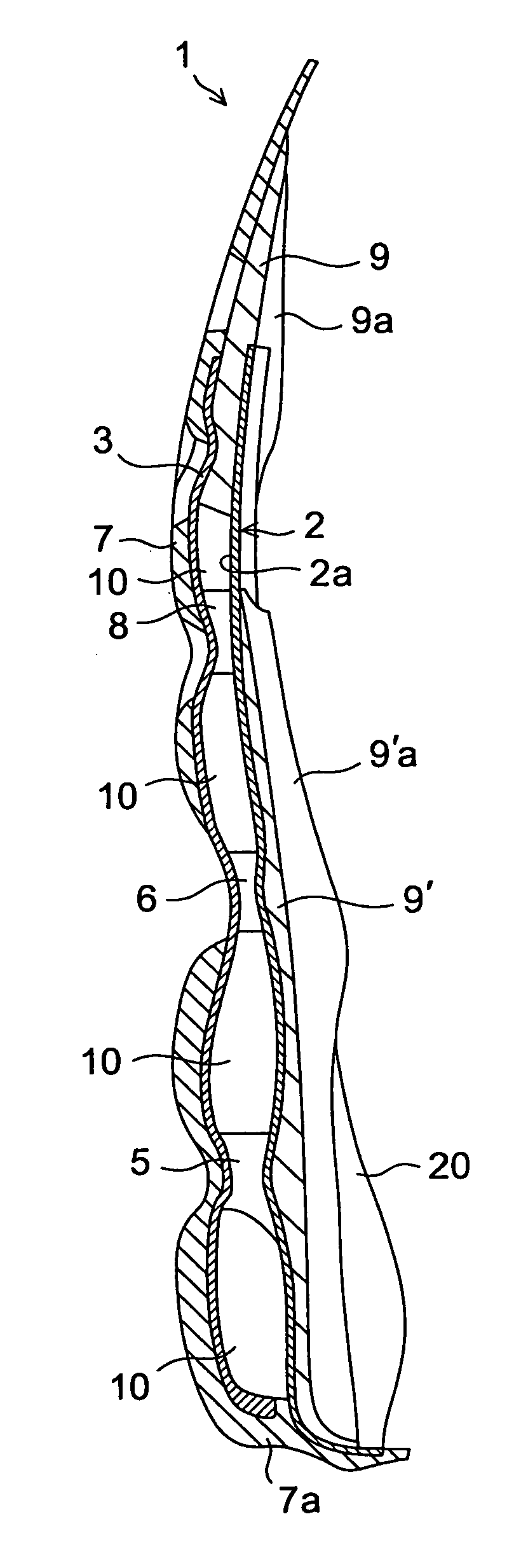
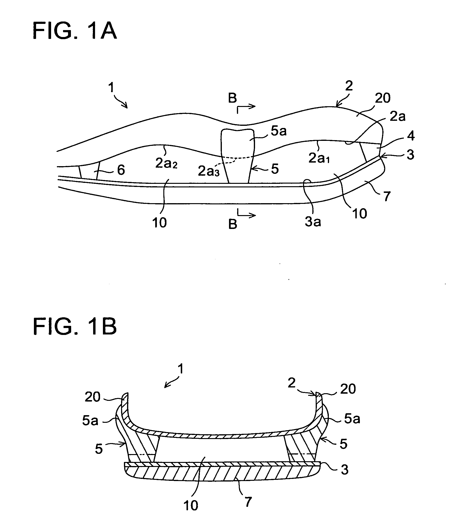
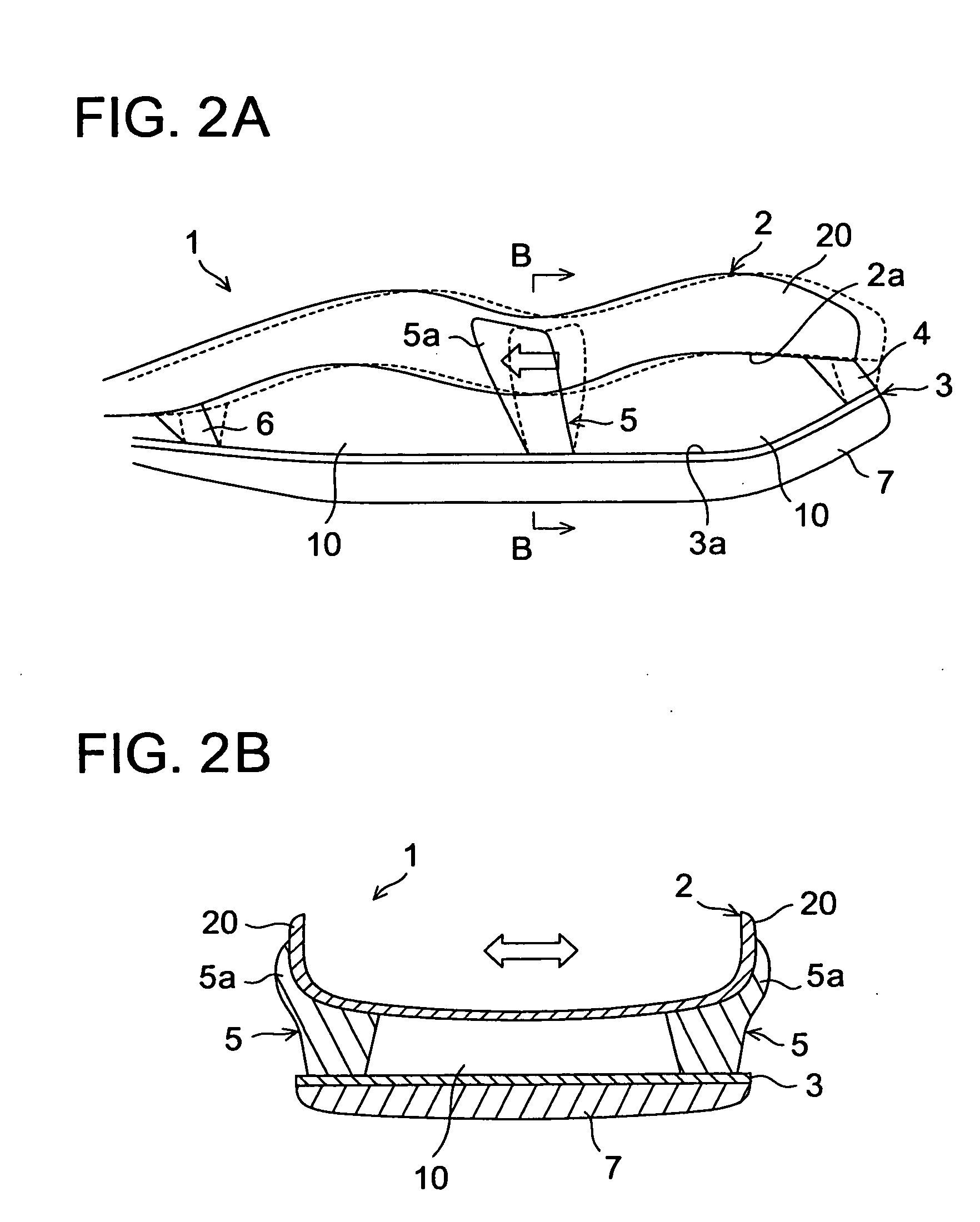
[0070]Referring now to the drawings, FIGS. 1 and 2 show a sole structure or a sole assembly for a shoe according to the present invention. In these drawings, like reference numbers indicate identical or functionally similar elements. Also, in FIG. 2A, a dotted line designates a state before deformation, which corresponds to FIG. 1A.

[0071]As shown in FIG. 1, a sole structure 1 comprises an upper plate 2 disposed on an upper side of the sole structure 1, a lower plate 3 disposed below the upper plate 2, a plurality of connecting portions 4, 5, 6 that are disposed and longitudinally (i.e. the left to right direction in FIG. 1A) separated between the upper plate 2 and the lower plate 3 to form a void 10 therebetween and that elastically connect a bottom surface 2a of the upper plate 2 with a top surface 3a of the lower plate 3. In this example, the bottom surface 2a of the upper plate 2 has a convexed and concaved shape formed of two upwardly convexedly curved portions 2a1, 2a2, and a d...

second embodiment

[0084]FIGS. 3 and 4 show a sole structure or a sole assembly for a shoe according to the present invention. In these drawings, like reference numbers indicate identical or functionally similar elements. Also, in FIG. 4A, a dotted line designates a state before deformation, which corresponds to FIG. 3A.

[0085]The second embodiment differs from the first embodiment in that the extension 5a at the upper end of the connecting portion 5 has longitudinally projecting portions 5b on the side surface of the upraised portion 20. That is, in this case, the connecting portion 5 is T-shaped in a side view. As shown in FIG. 3A, the longitudinally projecting portions 5b are hatched regions that extend from the extension 5a (see a longitudinal length d) of the connecting portion 5 toward the front and rear sides.

[0086]In this second embodiment as well, similar to the first embodiment, when the shoe impacts the ground the void 10 between the upper and lower plates 2, 3 compressively deforms to absor...

third embodiment

[0093]FIGS. 5 and 6 show a sole structure or a sole assembly for a shoe according to the present invention. In these drawings, like reference numbers indicate identical or functionally similar elements. Also, in FIG. 6A, a dotted line designates a state before deformation, which corresponds to FIG. 5A.

[0094]In the above-mentioned first and second embodiments, the upper plate 2 was solely convex-and-concave-shaped, but in this third embodiment, both the upper plate 2 and the lower plate 3 are convex-and-concave-shaped. That is, the top surface 3a of the lower plate 3 has a convex-and-concave-shape that is formed of two downwardly convexedly curved portions 3a1, 3a2, and an upwardly convexedly curved portion 3a3 disposed between the downwardly convexedly curved portions 3a1, 3a2. The upwardly convexedly curved portion 3a3 of the lower plate 3 is disposed opposite the downwardly convexedly curved portion 2a3 of the upper plate 2 and the connecting portion 5 is disposed between the upwa...


PUM


Abstract

A sole structure 1 for a shoe comprises an upper plate 2 that is disposed on the upper side of the structure 1 and that has upraised portions 20 projecting upwardly form opposite side edge portions of the upper plate 2, a lower plate 3 disposed below the upper plate 2, and a plurality of longitudinally separated connecting portions 4, 5 and 6 that are disposed between the upper plate 2 and the lower plates 3 to form voids 10 therebetween and that elastically connect the upper plate 2 with the lower plate 3. The upper end of the connecting portion 5 extends upwardly to the side surface of the upraised portion 20 of the upper plate 2 and a projecting portion 5b that projects in the longitudinal direction is provided at the extension 5a. The extension 5a and the projecting portion 5b are fixedly attached to the side surface of the upraised portion 20.

Description

BACKGROUND OF THE INVENTION[0001]The present invention relates generally to a sole structure for a shoe, and more particularly, to an improved sole structure for improving cushioning properties, causing a smooth ride feeling, and improving a lateral stability during walking or running.[0002]We proposed a sole structure such as shown in WO 2006 / 129837. The sole structure is comprised of an upper plate, a wavy corrugated lower plate disposed under the upper plate and having two bulges to form a void with the upper plate, and an elastic block to couple an upwardly convex portion formed between the adjacent bulges to the upper plate.[0003]Also, Japanese patent application laying-open publication No. 9-248203 (JP 9-248203) shows a midsole structure comprised of a dispersion portion formed of synthetic resin and disposed on the upper side of the structure, a ground contact portion disposed on the lower side of the structure, and a buffer portion formed of a plurality of longitudinally con...

Claims


Application Information

Patent Timeline
IPC IPC(8): A43B23/00A43B13/18
CPCA43B13/181
Inventor KITA, KENJIROSUZUKI, KAZUHIKOHORIOKA, TOSHIYA
Owner MIZUNO CORPORATION
Why Eureka
Try Eureka