
Multi-Vortex Flowmeter Employing Volume Flow Rate as Switching Point

a flowmeter and volume flow technology, applied in the direction of volume/mass flow by dynamic fluid flow effect, liquid/fluent solid measurement, instruments, etc., can solve the problem that the pressure in the flow tube is not taken into account at all, and achieve good accuracy and good accuracy

Inactive Publication Date: 2009-10-01
OVAL CORP
View PDF5 Cites 3 Cited by
  • Summary
  • Abstract
  • Description
  • Claims
  • Application Information

AI Technical Summary

Benefits of technology

The present invention relates to an improved multi-vortex flowmeter that uses a mass flow rate for a switching point. This allows for the selective use of a thermal flowmeter with good accuracy in measuring low flow rates. The invention also takes into account the fact that the vortex differential pressure increases when the pressure in the flow tube increases, even at low flow rates. By using the mass flow rate for the switching point, the invention addresses the problem of using a thermal flowmeter that does not provide accurate measurements at low flow rates. The invention also takes into account the fact that the switching point can be revised to enable the use of a thermal flowmeter with good accuracy. The technical effects of the invention include improved accuracy in measuring flow rates and the ability to select between a vortex flowmeter and a thermal flowmeter based on the mass flow rate.

Problems solved by technology

The inventor of the present application believes a problem lies in that a pressure in the flow tube is not taken into consideration at all.

Method used


Image

  • Multi-Vortex Flowmeter Employing Volume Flow Rate as Switching Point
  • Multi-Vortex Flowmeter Employing Volume Flow Rate as Switching Point
  • Multi-Vortex Flowmeter Employing Volume Flow Rate as Switching Point

Examples


Embodiment Construction

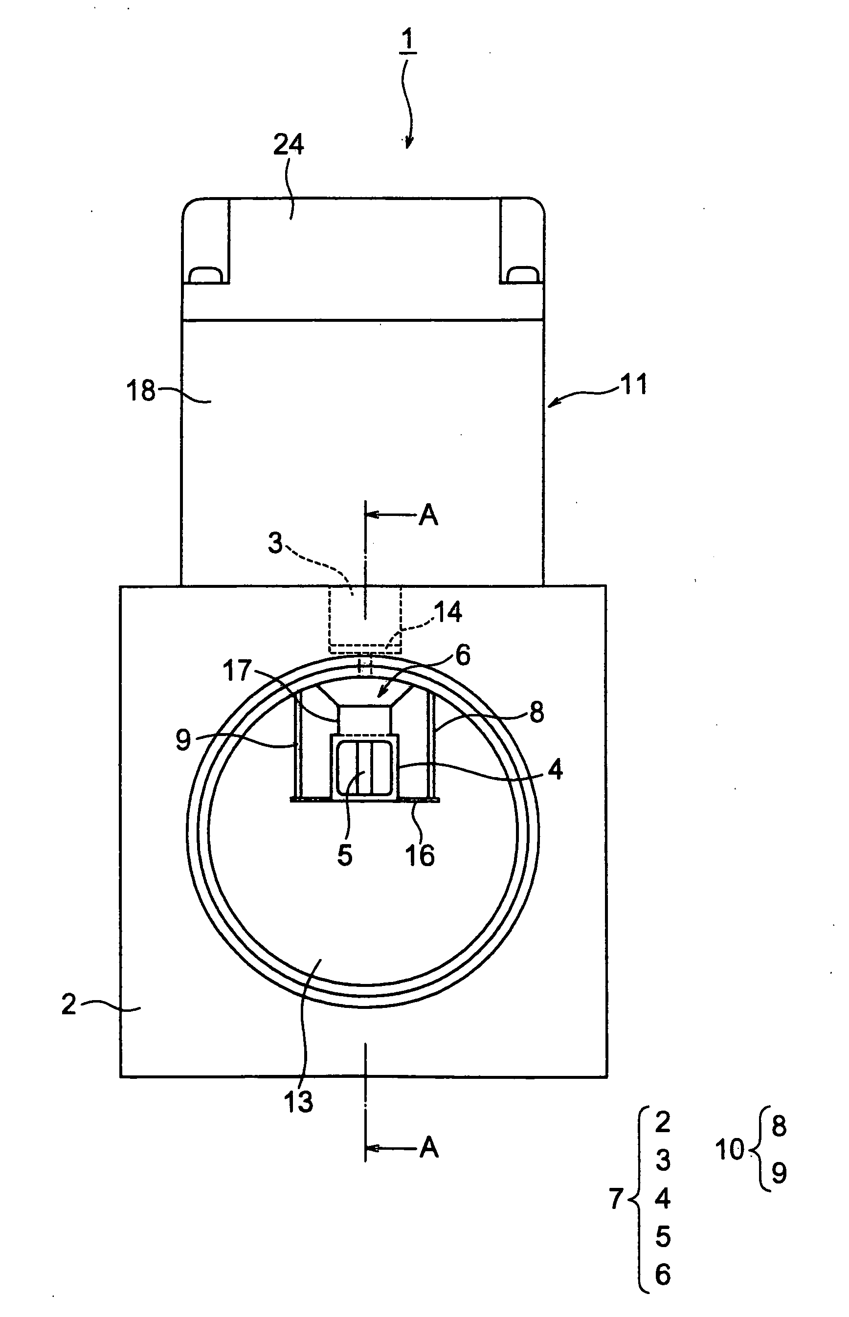
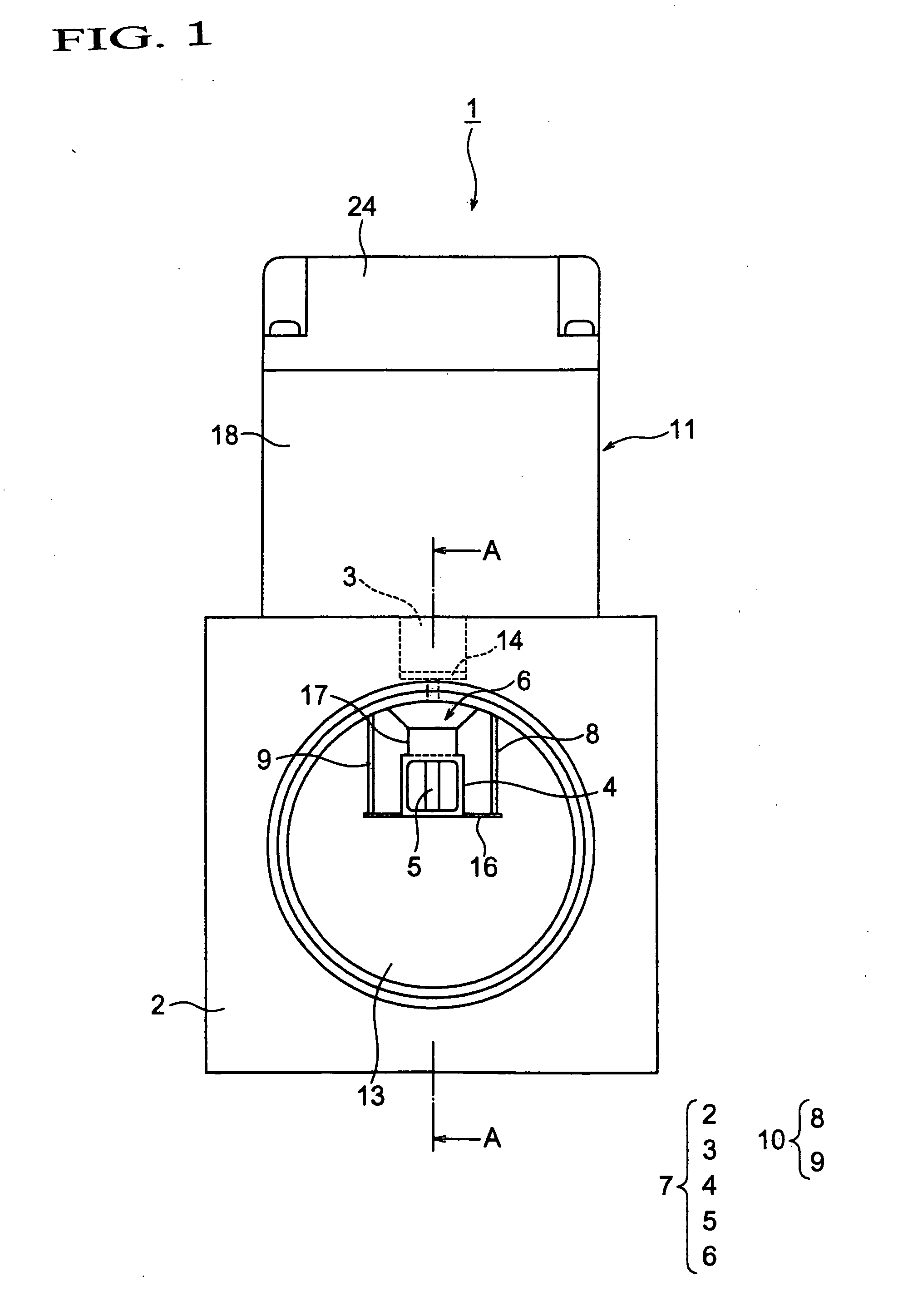
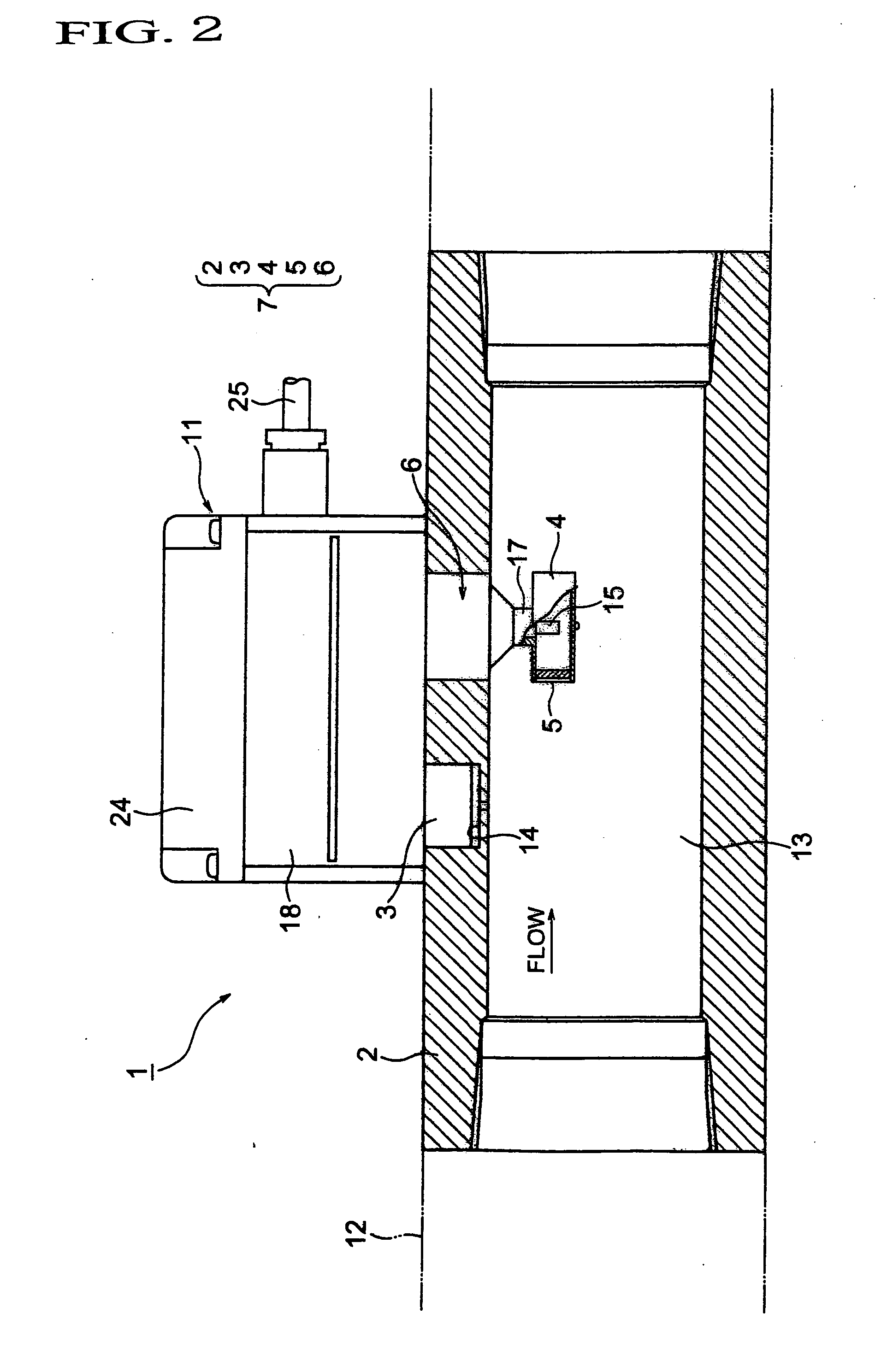
[0035]Hereinafter, the description is given referring to the accompanying drawings. FIG. 1 is a front view illustrating an embodiment of a multi-vortex flowmeter using a mass flow rate for a switching point according to the present invention. FIG. 2 is a sectional view taken along a line A-A in FIG. 1, and FIG. 3 is a sectional view of a flow rate converter. Furthermore, FIG. 4 is a view for illustrating the switching point, FIG. 5 is a view for comparison of the switching point, and FIG. 6 is a view for illustrating the switching point.

[0036]In FIGS. 1 and 2, the reference numeral 1 denotes a multi-vortex flowmeter according to the present invention. The multi-vortex flowmeter 1 is configured to have both a function of a vortex flowmeter and a function of a thermal flowmeter. Moreover, the multi-vortex flowmeter 1 is also configured to determine a switching point between the two flowmeters and to switch between the functions of the flowmeters based on the thus determined switching ...


PUM


Abstract

A multi-vortex flowmeter (1) includes a vortex flowmeter for measurement by volume flow rate and a thermal flowmeter for measurement by mass flow rate to selectively use the two flowmeters according to the flow rate of fluid to be measured flowing through a flow channel (13). The multi-vortex flowmeter (1) uses the mass flow rate for a switching point. In other words, the multi-vortex flowmeter (1) has the switching point of two flowmeters based on the mass flow rate. A mass flow rate Qm at the switching point in a range larger than the minimum flow rate of a vortex flowmeter and smaller than the maximum flow rate of a thermal flowmeter is determined by: Qm=K3*√P, (where, P is a pressure of the flow channel (variable), K3 is a constant determined by the area and the vortex differential pressure of the channel (13) and a constant related to the vortex differential pressure, a density at 0° C. and 1 atm, and the pressure at 1 atm). Alternatively, a volume flow rate Q at the switching point in a range larger than the minimum flow rate of a vortex flowmeter and smaller than the maximum flow rate of a thermal flowmeter is determined by: Q=K1 / √P, (where, P is a pressure of the channel (variable), K1 is a constant determined by the area and the vortex differential pressure of the flow channel (13) and a constant related to the density at 0° C. and 1 atm, and the pressure at 1 atm).

Description

TECHNICAL FIELD[0001]The present invention relates to a multi-vortex flowmeter including a vortex flowmeter for measurement by a volume flow rate and a thermal flowmeter for measurement by a mass flow rate, which uses the two flowmeters selectively depending on a flow rate of a fluid to be measured flowing through a flow channel, in particular, to a switching point between the two flowmeters.BACKGROUND ART[0002]In order to measure a flow rate of a fluid to be measured flowing through a flow tube, a vortex flowmeter and a thermal flowmeter are used.[0003]As is generally known, the vortex flowmeter makes use of the fact that the number of Karman vortexes (vortex frequency) generated by a vortex generator in a unit time is proportional to a flow rate within a predetermined Reynolds number range regardless of whether the vortex generator is a gas or a liquid when the vortex generator is placed in a fluid flow. The constant of proportionality is referred to as the Strouhal number. As vor...

Claims


Application Information

Patent Timeline
Patent Type & Authority Applications(United States)
IPC IPC(8): G01F1/32G01F1/68
CPCG01F1/3209G01F1/3254G01F7/00G01F1/86G01F1/684G01F1/3259
Inventor MATSUBARA, NAOKITAKAHASHI, KOHJI
Owner OVAL CORP
Learn More