Radiological measurement system and radiological imaging system

a radiological imaging and measurement system technology, applied in the direction of x/gamma/cosmic radiation measurement, instruments, radioation controlled devices, etc., can solve the problems of hampered achieve minimum dead time, prevent surge current from entering the amplifier, and ensure temporal continuity of measurement

Inactive Publication Date: 2009-10-01
HITACHI LTD
View PDF5 Cites 6 Cited by
  • Summary
  • Abstract
  • Description
  • Claims
  • Application Information

AI Technical Summary

Benefits of technology

[0020]From such a viewpoint, an object of the present invention is to provide a radiological measurement system and a radiological imaging system capable of protecting the amplifier from damage caused by the surge current and ensuring the temporal continuity of the measurement with a minimum dead time.
[0021]As means for attaining the object, a radiological measurement system is a radiological measurement system including a radiation detector formed of semiconductor crystal, a high voltage DC supply for applying a bias voltage to the radiation detector, a controller provided between the radiation detector and the high voltage DC supply to exercise on-off control on the bias voltage supplied from the high voltage DC supply, an amplifier for amplifying a detected signal supplied from the radiation detector, and a protection circuit provided between the radiation detector and the amplifier to protect the amplifier from a surge current generated when the bias voltage is subjected to the on-off control. The radiological measurement system includes a control unit for preventing the surge current from flowing to the amplifier, and a switch provided in parallel with the protection circuit and controlled in operation state by the control unit. The control unit controls the operation state of the switch in synchronism with the on-off control exercised by the control unit to prevent the surge current from flowing to the amplifier. Over the time period during which the bias voltage is made zero, therefore, operation of an input to the amplifier can be stopped. Thus, it is possible to prevent the surge current from entering the amplifier and prevent the dead time from being caused by saturation.
[0022]According to the present invention, a radiological measurement system and a radiological imaging system capable of protecting the amplifier from damage caused by the surge current and ensuring the temporal continuity of the measurement with a minimum dead time are obtained.

Problems solved by technology

However, providing such a protection circuit poses a problem that a dead time which is far longer than the time period required to make the bias voltage zero occurs and the temporal continuity of the measurement is hampered.
This is a problem common to radiological measurement in the radiological measurement system and the radiological imaging system.

Method used


Image

  • Radiological measurement system and radiological imaging system
  • Radiological measurement system and radiological imaging system
  • Radiological measurement system and radiological imaging system

Examples


first embodiment

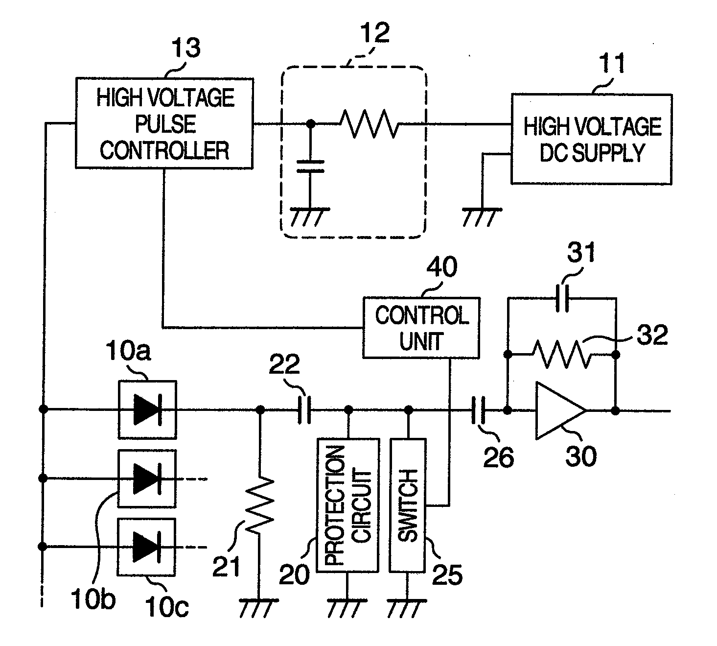
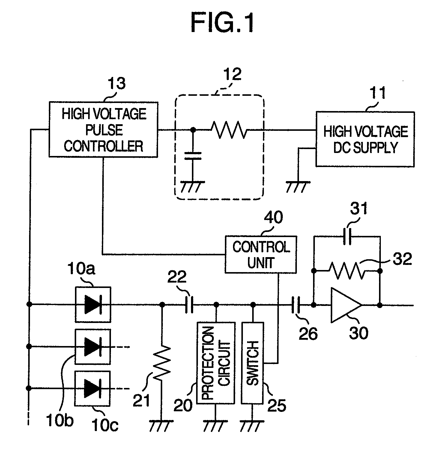
[0031]A radiological measurement system according to the present embodiment includes mainly radiation detectors 10a (10b, 10c), a high voltage DC supply 11 serving as a power supply, a high voltage pulse controller 13 functioning as a controller, an amplifier 30, a protection circuit 20, a switch 25, and a control unit 40.

[0032]The radiological measurement system includes a plurality of radiation detectors 10a, 10b, 10c Each of them is connected on the downstream side of the high voltage pulse controller 13, and has a signal processing circuit such as the amplifier 30. In the ensuing description, a circuit connected to one radiation detector 10a is taken as an example.

[0033]In the radiation detector 10a, a region which causes reaction with radiations and generates charges is formed of single crystal of semiconductor such as cadmium telluride. A pn junction diode is formed by using, for example, a cathode which has Pt as its principal component and an anode which has In as its princi...

second embodiment

[0071]In a radiological measurement system according to a second embodiment, the switch 25 (see FIG. 1) is not provided in parallel with the protection circuit 20, but a voltage regulating device 50 which can be controlled in connection intermission by the control unit 40 is provided between the capacitor 26 and the amplifier 30 as shown in FIG. 6.

[0072]The voltage regulating device 50 is a device which can supply a constant voltage. The voltage regulating device 50 can be connected to the input side of the amplifier 30. Timing of the connection is the same as that in the case of the switch 25 (see FIG. 1) described in the first embodiment. In other words, at the time of the off-control of the bias voltage, the control unit 40 exercises control so as to bring the voltage regulating device 50 and the amplifier 30 into a connection state and then exercise off-control on the bias voltage. At the time of the on-control of the bias voltage, the control unit 40 exercises control so as to ...


PUM


Abstract

A radiological measurement system protecting an amplifier from damage caused by a surge current, ensuring temporal continuity of measurement with a minimum dead time, and including a high voltage DC supply for applying a bias voltage to a radiation detector formed of semiconductor crystal, a controller for exercising on-off control on the bias voltage supplied from the high voltage DC supply, an amplifier, a protection circuit for protecting the amplifier from a surge current generated when the bias voltage is subjected to the on-off control, a control unit for preventing the surge current from flowing to the amplifier, and a switch provided in parallel with the protection circuit and controlled in operation state by the control unit, wherein the control unit controls the operation state of the switch in synchronism with the on-off control exercised by the control unit to prevent the surge current from flowing to the amplifier.

Description

BACKGROUND OF THE INVENTION[0001]The present invention relates to a radiological measurement system and a radiological imaging system.[0002]As a detector in the radiological measurement system, there are an ionization chamber, a scintillation detector, a semiconductor detector, and a cumulative radiation monitor. They are used properly according to the use. If it is desired to obtain not only a dose of gamma rays or X-rays but also its energy information, then the semiconductor detector is typically used. If gamma rays or X-rays are incident on a semiconductor, then the gamma rays or X-rays undergo energy conversion and a large amount of carrier charges such as electrons or holes are generated and the charge quantity is proportional to energy of the gamma rays or X-rays. In other words, since the energy can be known by measuring the charge quantity, high precision measurement results are obtained.[0003]In the scintillation detector as well, energy can be found by converting gamma ra...

Claims


Application Information

Patent Timeline
Patent Type & Authority Applications(United States)
IPC IPC(8): G01T1/24
CPCG01T1/24
Inventor SEINO, TOMOYUKIISHITSU, TAKAFUMIUENO, YUICHIRO
Owner HITACHI LTD
Why Eureka
Try Eureka