
Power supply apparatus and power control method

a power supply apparatus and power control technology, applied in the direction of dc network circuit arrangement, dc source parallel operation, electrochemical generators, etc., can solve the problem that the system does not take into account the power loss attributed to the diode or circui

Inactive Publication Date: 2009-10-01
KK TOSHIBA
View PDF3 Cites 37 Cited by
  • Summary
  • Abstract
  • Description
  • Claims
  • Application Information

AI Technical Summary

Problems solved by technology

However, the system does not take into consideration power loss attributed to the diode OR circuit.

Method used


Image

  • Power supply apparatus and power control method
  • Power supply apparatus and power control method
  • Power supply apparatus and power control method

Examples


Embodiment Construction

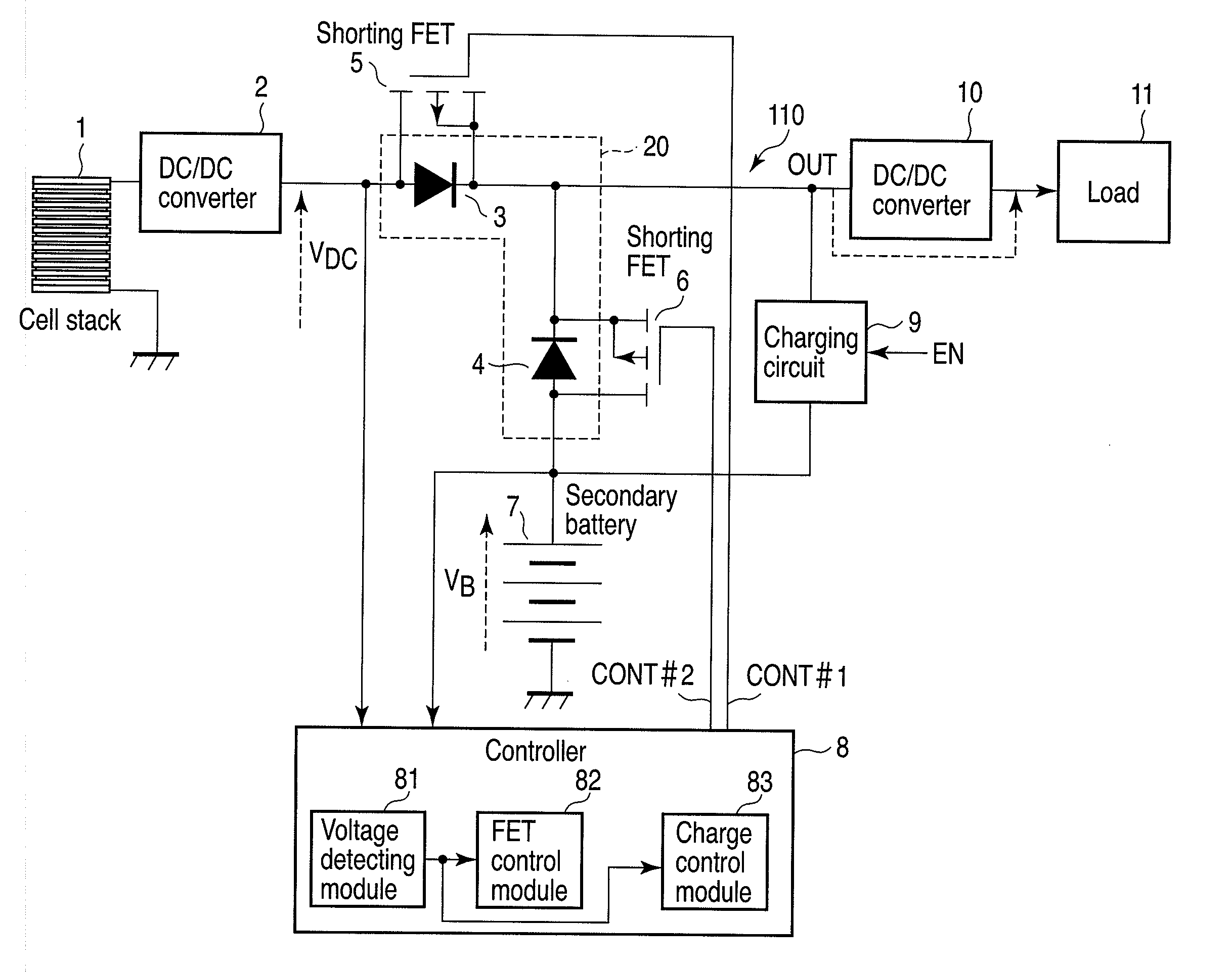
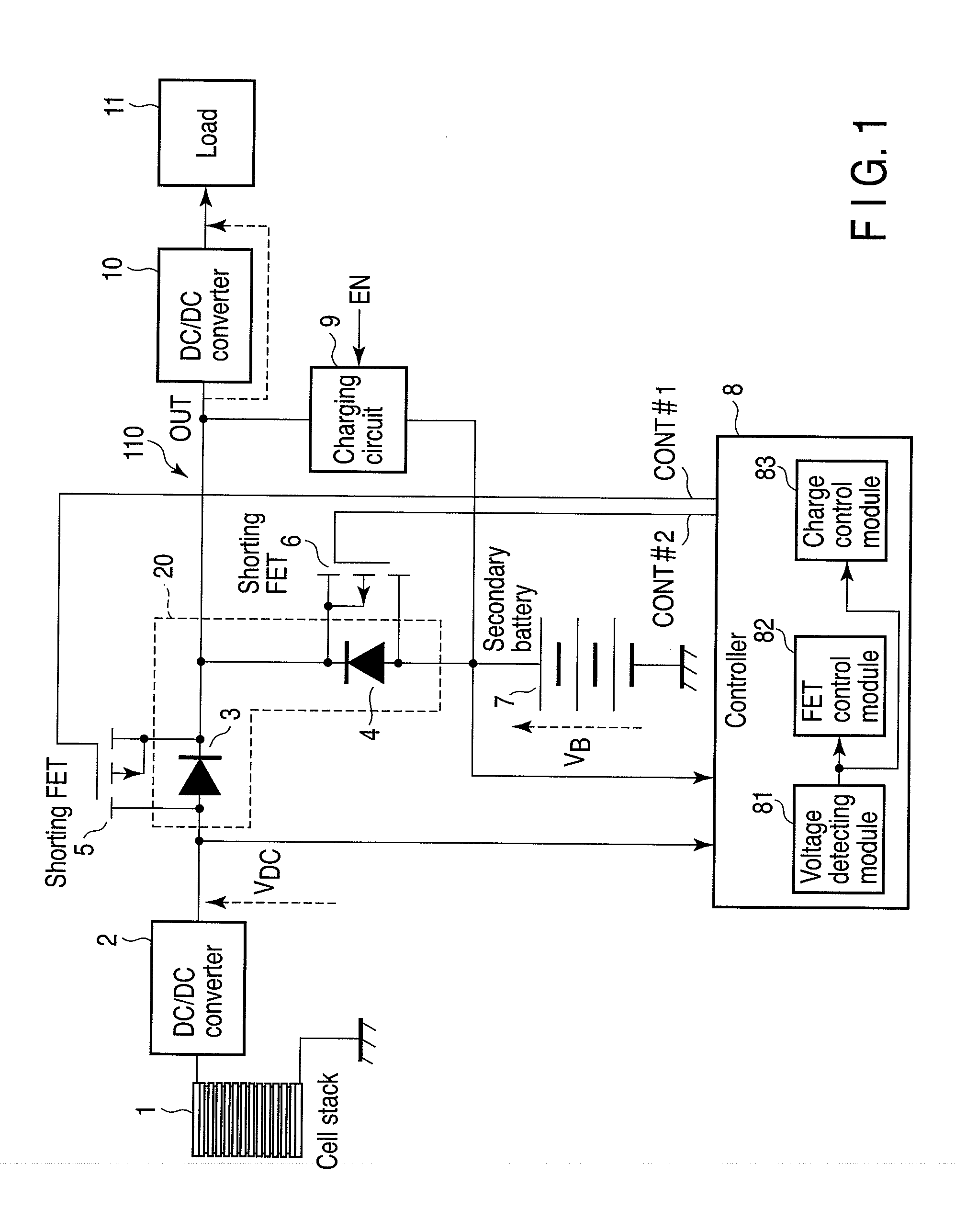
[0016]Various embodiments according to the invention will be described hereinafter with reference to the accompanying drawings. In general, according to one embodiment of the invention, there is provided a power supply apparatus comprising: a DC / DC converter coupled to an output of a fuel cell, and configured to have a characteristic such that an output voltage of the DC / DC converter drops with increasing an output current of the DC / DC converter; a first diode connected between the output of the DC / DC converter and an output terminal of the apparatus; a second diode connected between an output of a secondary battery and the output terminal, the second diode having the same forward voltage drop as that of the first diode; a first transistor which has a current path connected in parallel with the first diode; a second transistor which has a current path connected in parallel with the second diode; and a control module configured to monitor the output voltage of the DC / DC converter and...


PUM


Abstract

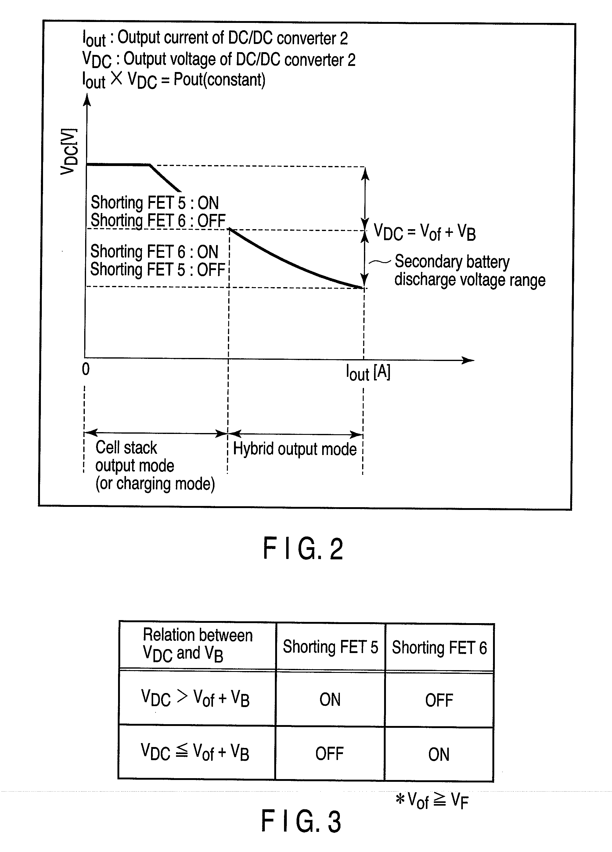
According to one embodiment, a power supply apparatus comprises a DC / DC converter coupled to an output of a fuel cell, a first diode connected between the output of the DC / DC converter and an output terminal of the apparatus, a second diode connected between an output of a secondary battery and the output terminal, a first transistor connected in parallel with the first diode, a second transistor connected in parallel with the second diode, and a control module configured to set the first and the second transistor to the off and the on state, respectively, when the output voltage of the DC / DC converter is equal to or lower than a reference voltage, and to set the first and the second transistor to the on and the off state, respectively, when the output voltage of the DC / DC converter is higher than the reference voltage.

Description

CROSS-REFERENCE TO RELATED APPLICATIONS[0001]This application is based upon and claims the benefit of priority from Japanese Patent Application No. 2008-078737, filed Mar. 25, 2008, the entire contents of which are incorporated herein by reference.BACKGROUND[0002]1. Field[0003]One embodiment of the present invention relates to a power supply apparatus for use in electronic equipment, such as a personal computer, and a method of control thereof, and more particularly to a power supply apparatus which uses a fuel cell as a power source and a method of control thereof.[0004]2. Description of the Related Art[0005]Heretofore, a lithium ion battery has been used as a power source in portable electronic equipment, such as a notebook computer. Recently, in portable electronic equipment as well, a fuel cell has received attention as a new power source which replaces the lithium ion battery.[0006]A fuel cell adapted for use in portable electronic equipment requires reduction in size. For this...

Claims


Application Information

Patent Timeline
Patent Type & Authority Applications(United States)
IPC IPC(8): H02J1/00
CPCH01M16/003H02J2001/004H02J7/34H02J2300/30Y02E60/50
Inventor OTO, KATSUYA
Owner KK TOSHIBA
Learn More