Battery Charging Apparatus and Method

a battery charger and battery technology, applied in the direction of electrochemical generators, secondary cell servicing/maintenance, transportation and packaging, etc., can solve the problems of large heat, non-functional battery, and non-compliance of battery chargers including such transformers with european standards

Inactive Publication Date: 2009-10-01
SPX CORP
View PDF3 Cites 142 Cited by
  • Summary
  • Abstract
  • Description
  • Claims
  • Application Information

AI Technical Summary

Problems solved by technology

Because this crystalline lead sulfate is not a strong conductor of electricity, when too much crystalline lead sulfate has formed, the battery becomes non-functional.
However, the battery chargers currently available to reverse the sulfation process make use of transformers that are heavy (i.e., that often weigh 100 pounds or more) and that generate a large amount of heat.
In addition to being heavy and generating a large amount of heat, the above-discussed transformers also do not have power factors of between 0.95 and 1.0.
Hence, battery chargers including such transformers do not meet European standards and therefore cannot obtain Conformite Europeene (CE) markings.
Further, because the above-mentioned transformers are effectively hard-wired to operate at a particular voltage, currently available battery chargers capable of at least partially reversing the sulfation process cannot be operated both at locations solely providing voltage levels of 120V and at locations solely providing voltage levels of 220V.

Method used


Image

  • Battery Charging Apparatus and Method
  • Battery Charging Apparatus and Method

Examples


Embodiment Construction

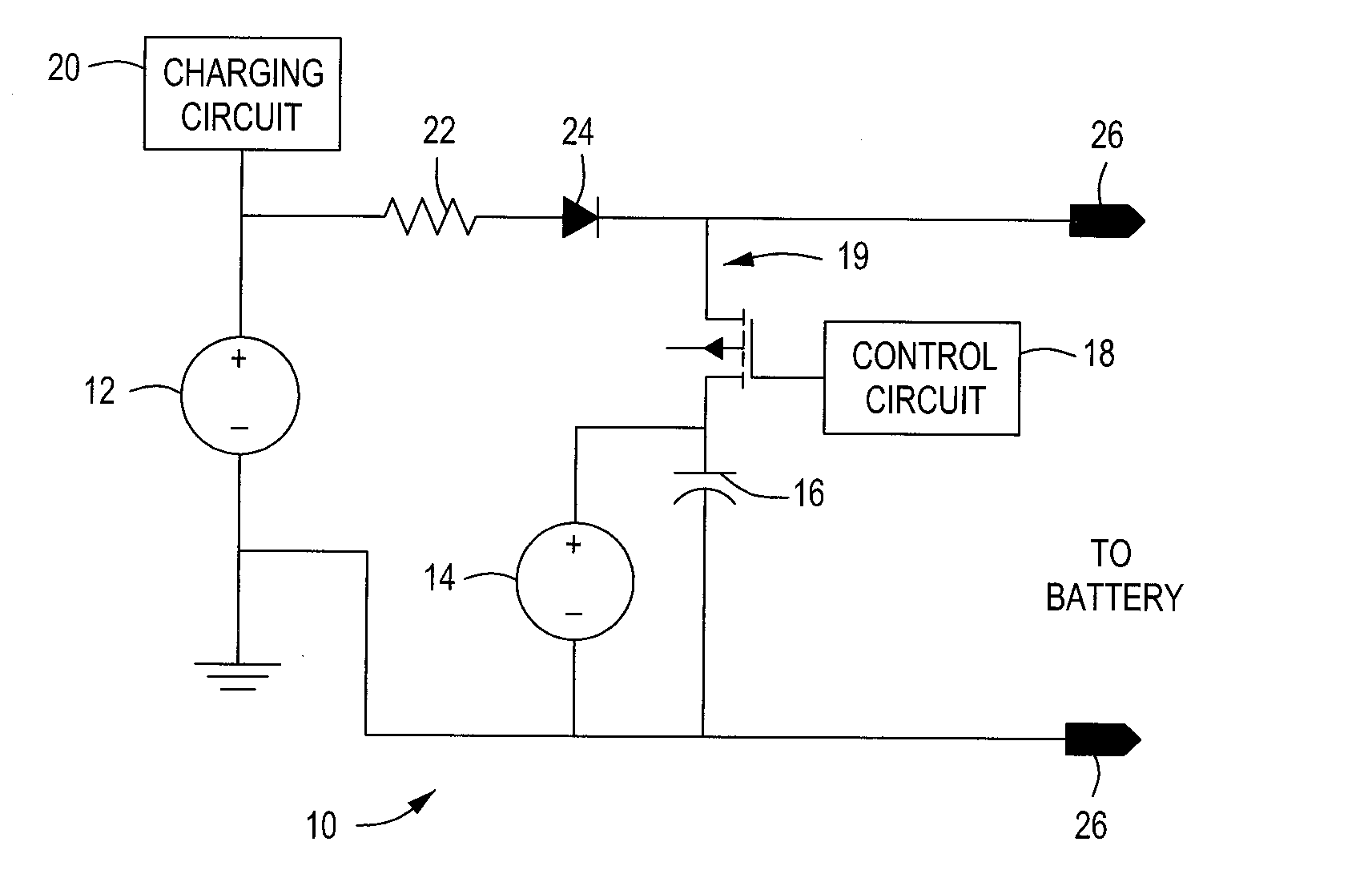
[0015]The invention will now be described with reference to the drawing figures, in which like reference numerals refer to like parts throughout. FIG. 1 illustrates a circuit diagram 10 of a battery charger according to an embodiment of the present invention. The circuit diagram 10 includes a primary switching-mode power supply 12, a secondary switching-mode power supply 14, a capacitor 16, a control circuit 18, a switch 19, a charging circuit 20, a shunt resistor 22, a diode 24 and a pair of battery leads 26 that are all, either directly or indirectly, electrically connected to each other.

[0016]The switching-mode power supplies 12, 14 are electronic power supply units that each include a switching regulator therein. More specifically, each of the switching-mode power supplies 12, 14 actively switches a transistor included therein between full saturation (i.e., an “on” position) and full cutoff (i.e., an “off” position) at a high rate. This turns alternating current (AC) input into ...


PUM


Abstract

A battery charger that includes a primary switching-mode power supply, a secondary switching-mode power supply and a capacitor that is electrically connected to these two power supplies. In operation, this battery charger may be used to reverse the sulfation process in a battery. Also, a battery charging method that may be used to reverse the sulfation process in a battery.

Description

FIELD OF THE INVENTION[0001]The present invention relates generally to battery chargers and methods for the operation thereof. More particularly, the present invention relates to battery chargers and battery charging methods for vehicular and larger batteries.BACKGROUND OF THE INVENTION[0002]Lead-acid batteries, which are frequently found in cars, trucks, boats and other vehicles, typically include a set of plate electrodes that themselves include lead and lead oxide. These electrodes are usually encased in a battery housing and immersed in a sulfuric acid-based electrolyte.[0003]While in operation, the above-mentioned chemical components of lead-acid batteries react with each other to form an amorphous lead sulfate. Then, when such batteries are being recharged, much of the amorphous lead sulfate is converted back into a combination of lead, lead oxide and sulfuric acid. However, over time, a more stable crystalline lead sulfate also forms within a battery. Because this crystalline...

Claims


Application Information

Patent Timeline
Patent Type & Authority Applications(United States)
IPC IPC(8): H02J7/00
CPCH01M10/06H02J7/0052H01M10/44H01M10/4264H02J7/00Y02E60/10
Inventor ANDELFINGER, RICHARD L.
Owner SPX CORP
Why Eureka
Try Eureka