Eureka AIR delivers breakthrough ideas for toughest innovation challenges, trusted by R&D personnel around the world.

System and method for automatically generating virtual world environments based upon existing physical environments

a virtual world environment and system technology, applied in the field of automatic generation of virtual world environments based upon existing physical environments, can solve the problems of laborious, difficult physical management of servers, networking devices, other mission-critical equipment within a data center, and inaccurate depiction of a real physical environmen

Inactive Publication Date: 2009-10-01
IBM CORP
View PDF24 Cites 20 Cited by
  • Summary
  • Abstract
  • Description
  • Claims
  • Application Information

AI Technical Summary

Benefits of technology

[0009]Another embodiment of the present invention comprises a computer program product embodied in a computer readable medium for operating in a system comprising a network I/O, a CPU, and one or more databases, for implementing a method for automatically creating virtual renditions of at least one physical resource to replicate a real-life environment in a system having a virtual world gateway, a virtual world rendering module and at least one physical resource, the virtu

Problems solved by technology

Physical management of servers, networking devices, and other mission-critical equipment within a data center is very challenging.
Additionally, it is common practice for businesses to staff a primary production data center, where secondary back-up data centers may exist and be unstaffed.
Often, virtual world regions, areas, and objects are created from scratch, which is very labor intensive, and may also be inaccurate when depicting a real physical environment.
When creating a virtual data center with many physical resources and location identities, it is very time-consuming to create such environments manually.

Method used


Image

  • System and method for automatically generating virtual world environments based upon existing physical environments
  • System and method for automatically generating virtual world environments based upon existing physical environments
  • System and method for automatically generating virtual world environments based upon existing physical environments

Examples


embodiment 300

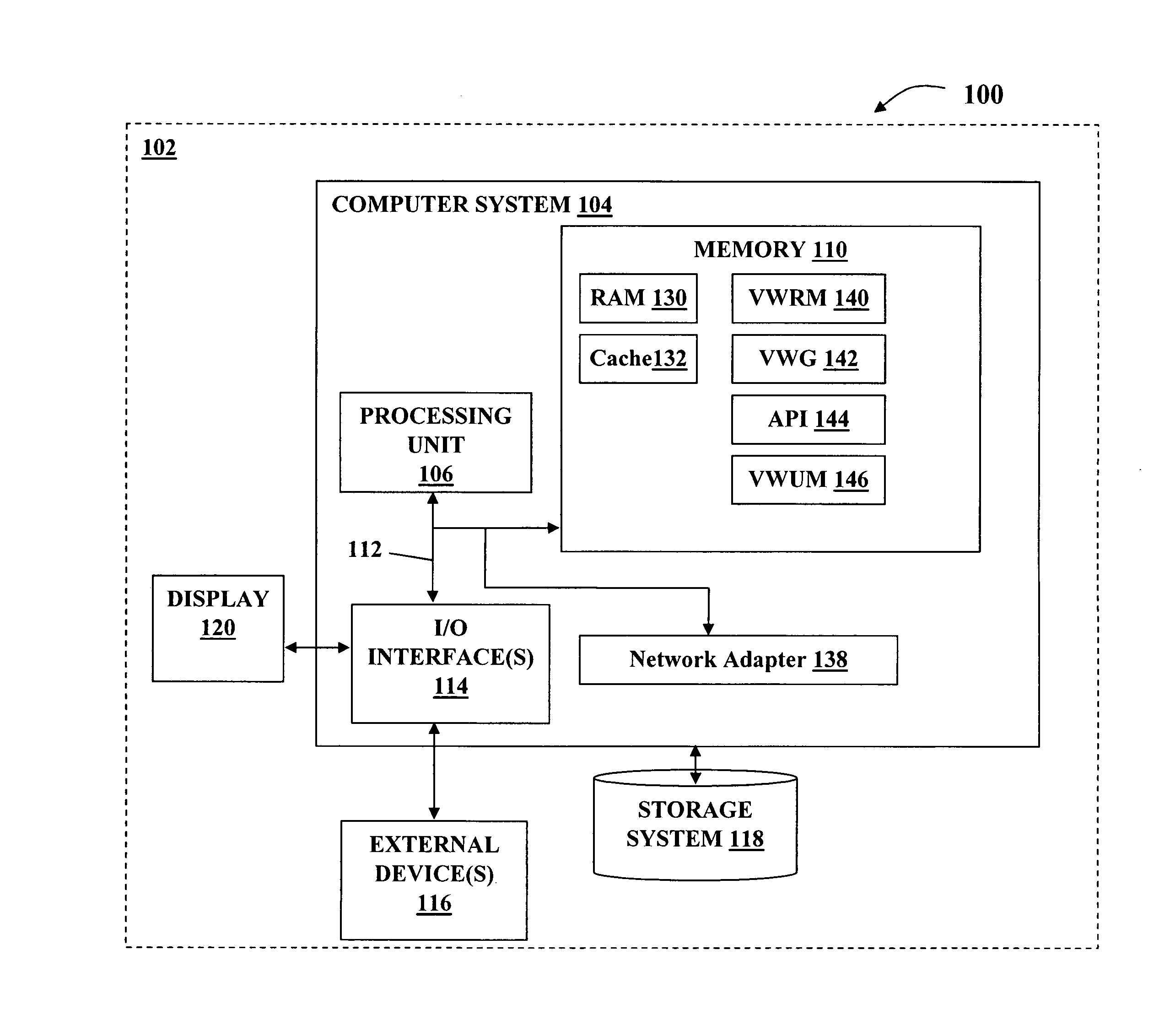
[0032]FIG. 3 depicts one possible embodiment 300 of this invention which utilizes a Virtual World Gateway (VWG) 142, acting as an interface between physical resources such as legacy I / T management systems (floor plan data 310, asset data 312, location tracking data 314 of I / T Equipment 316, for example) and the Virtual World Rendering Module (VWRM) 140. Many standards exist in the I / T industry, such that, creating an API 144 to translate standard I / T data (floor plan data 310, asset data 312, location tracking data 314) to the Virtual World Rendering Module 140 is possible. The Virtual World Gateway 142 receives descriptive resource data (floor plan data 310, asset data 312, location tracking data 314) through the API 144 from a legacy source, translates that data so that it is utilized by the VWRM 140, which in turn would create the Virtual World Graphic Representation 308 of the resource. As noted above, FIG. 3 depicts these logical relationships. For the purposes of this applicat...

embodiment 700

[0058]FIG. 7 illustrates an Alternate Virtual World SIMM Embodiment 700 wherein I / T Equipment 712 has its own Agent 714 for monitoring the configuration and changes to the configuration and passes this data directly to SIMM 701 having VWG 142, VIUM 146, API & Agent 144, and VWRM 140 for producing VWGR 308 per prior discussions above.

[0059]FIG. 9 illustrates an Example 3D Data Center Update 900 illustrating a Pre-change rendering 902 and a Post-change rendering 904 wherein, in the Pre-change rendering 902, Rack 17906 having Server A—p570 912 in Location AE-12 916 and Rack 18 908 having Server B—p570 914 in Location AE-13 918. In the Post-change rendering 904, Rack 17 906 has both Server A—p570 912 and Server B—p570 914 in Location AE-12 916.

[0060]The present invention further comprises a method for deploying a system for automatically creating a virtual rendition of at least one physical resource to replicate a real-life environment, the system comprising a virtual world gateway conn...


PUM


Abstract

In general, the present invention provides a system and method for creating and utilizing virtual worlds for enhanced management of an Information Technology (IT) environment. Two dimensional (2D) and / or three dimensional (3D) virtual world renditions are automatically created to replicate the associated real-life IT environment. Such virtual environments can then be used to familiarize staff with remote locations and to securely provide virtual data center tours to others. This invention comprises a system and method of automatically creating a virtual world environment to reflect a real world environment using information stored in databases and floor plans. The virtual world environment is rendered utilizing a Virtual World Rendering Module and is updated utilizing a Virtual Instrument Update Module.

Description

FIELD OF THE INVENTION[0001]Aspects of the present invention provide a system and method for utilizing virtual environments to provide an accurate view of real world facilities and resources. Using an embodiment of the present invention, the two dimensional (2D) and three dimensional (3D) virtual renditions of physical resources are automatically created to replicate real-life environments, such as computer data centers and other trackable assets.BACKGROUND OF THE INVENTION[0002]Information technology (IT) systems are often housed in raised floor computer room areas within a data center environment. The servers and networking equipment are often stacked in racks and organized in rows. Many IT environments keep asset management databases recording the location and status of various assets, including servers and network devices. They may also have blueprints or floor plans showing the location of racks and equipment within a room. Tracking and documenting the location, relocation, upg...

Claims


Application Information

Patent Timeline
IPC IPC(8): G06T15/00
CPCG06T15/00
Inventor KULKARNI, GAURAV N.HAMILTON, II, RICK A.SAND, ANNE R.SEAMAN, JAMES W.
Owner IBM CORP
Why Eureka
Eureka Blog
Learn More