

Arrow having an insert head assembly and fletching design
- Summary
- Abstract
- Description
- Claims
- Application Information
AI Technical Summary
Benefits of technology
Problems solved by technology
Method used
Image

Examples
Embodiment Construction
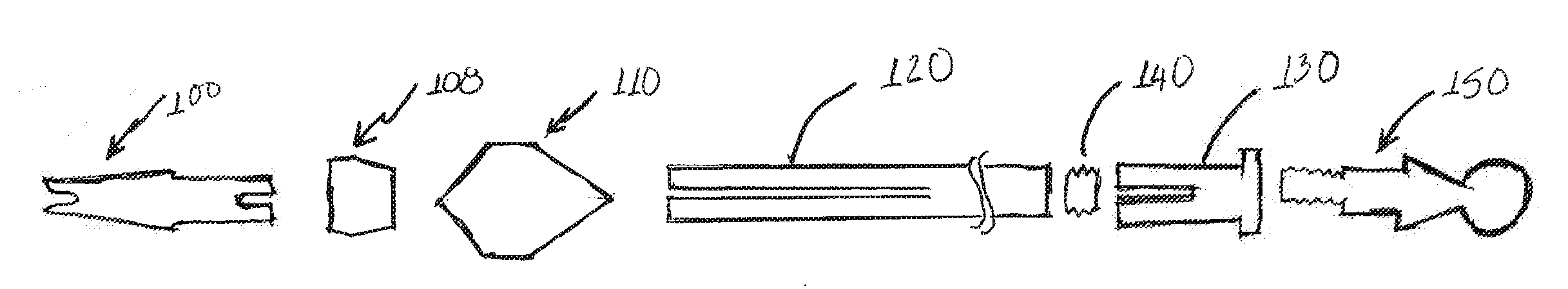
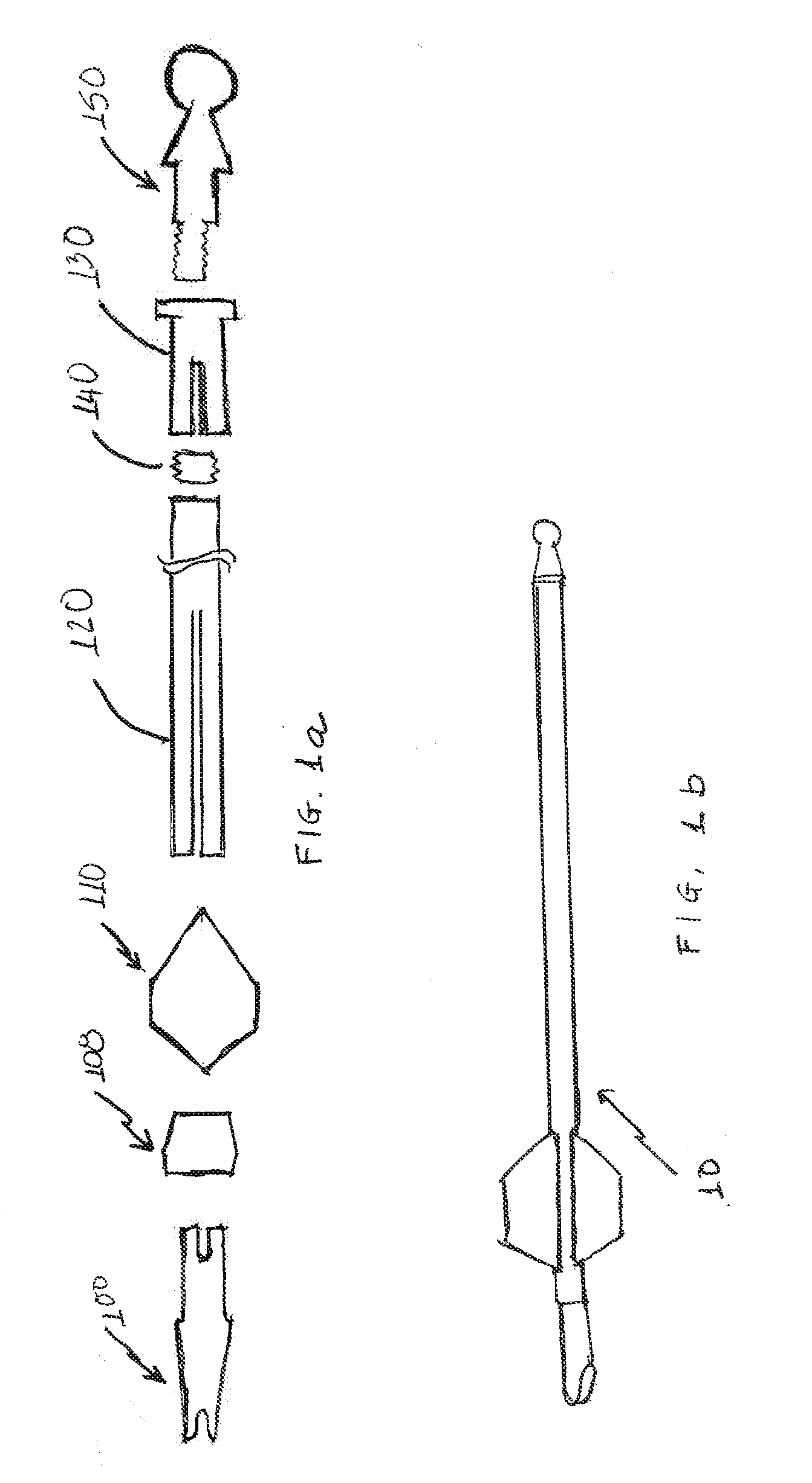
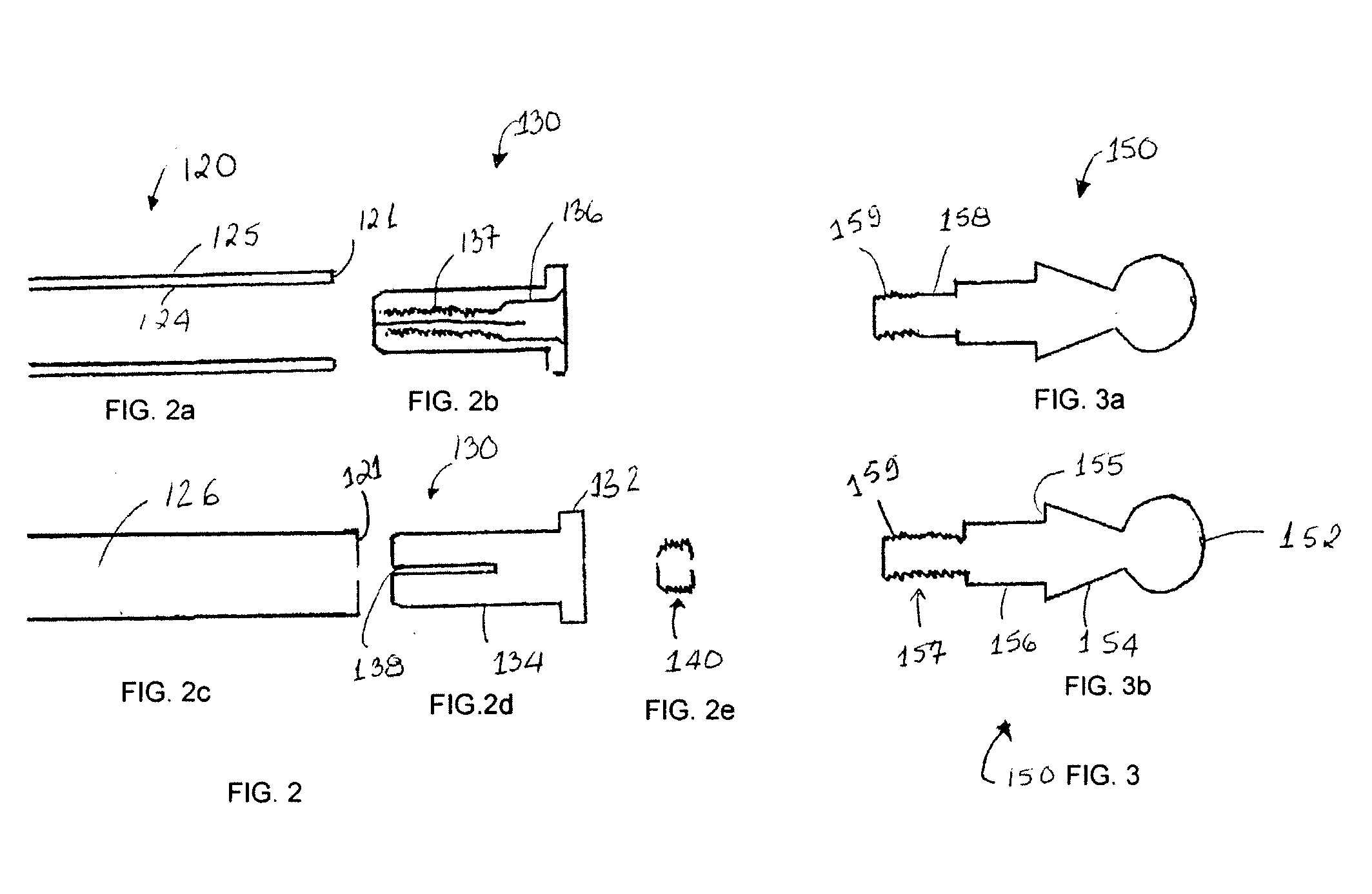
[0021]The present invention provides arrow assemblies for use in target shooting as well as hunting. With reference to FIG. 1, there is shown an exemplary arrow assembly 10 according to the invention. FIG. 2 shows an exploded view of various components of the arrow assembly of FIG. 1. The arrow assembly 10 includes a shaft 120, an arrow head 150, a locking insert 130 for receiving the arrow head, a fletching assembly 110, and a nock assembly 100.
[0022]In the exemplary embodiment of FIG. 1, the arrow assembly 10 includes an arrow shaft 120 having a longitudinal hollow shaft body 126 on which an arrow head 150, fletching 110 and nock are mounted. The shaft 120 may be made of any other suitable material including metal, e.g., aluminum, plastic, wood, graphite and / or a composite material. In one embodiment, the shaft 120 is made from a light weight material such as aluminum or fiber reinforced plastic. Some examples of fiber reinforced plastic materials include, but are not limited to, ...
PUM
 Abstract
Description
Claims
Application Information