Mass-flow throttle for large natural gas engines

Pending Publication Date: 2022-05-05
ECONTROLS
View PDF15 Cites 2 Cited by
  • Summary
  • Abstract
  • Description
  • Claims
  • Application Information

AI Technical Summary

Benefits of technology

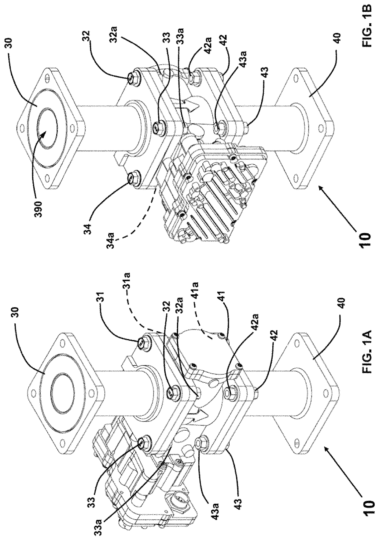
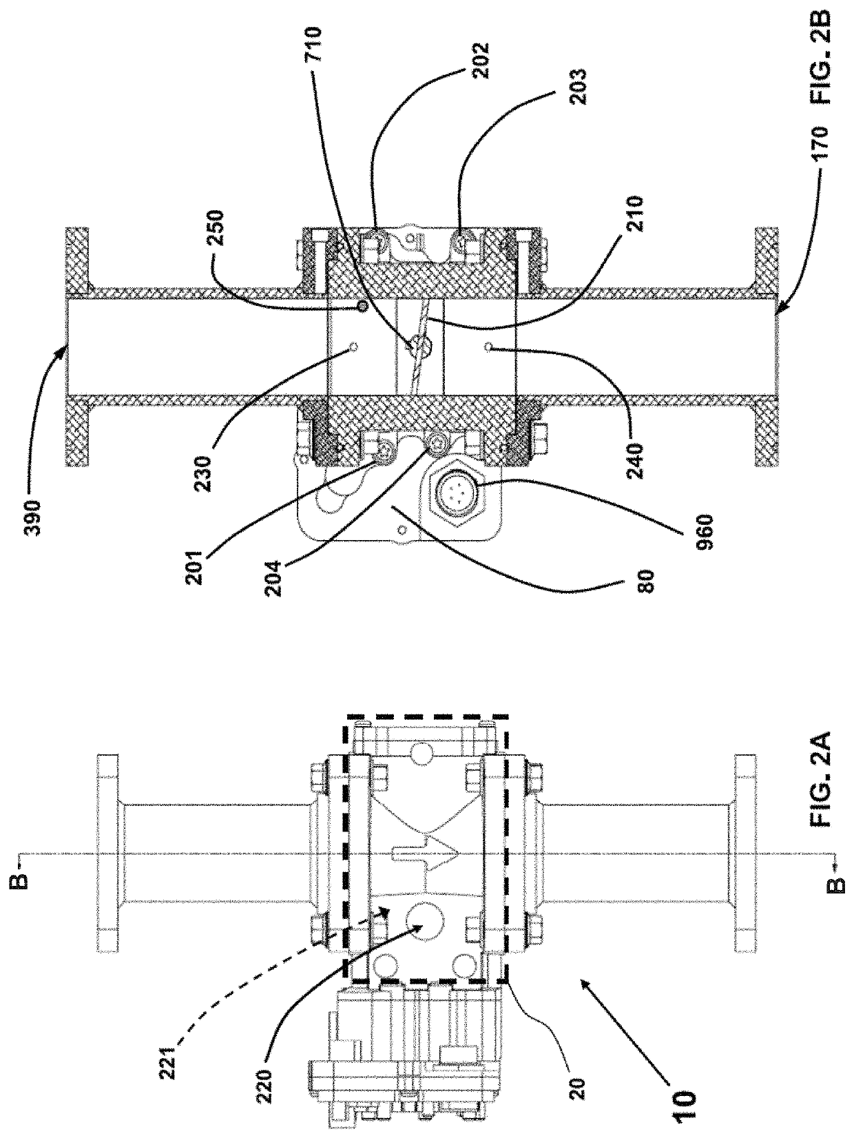
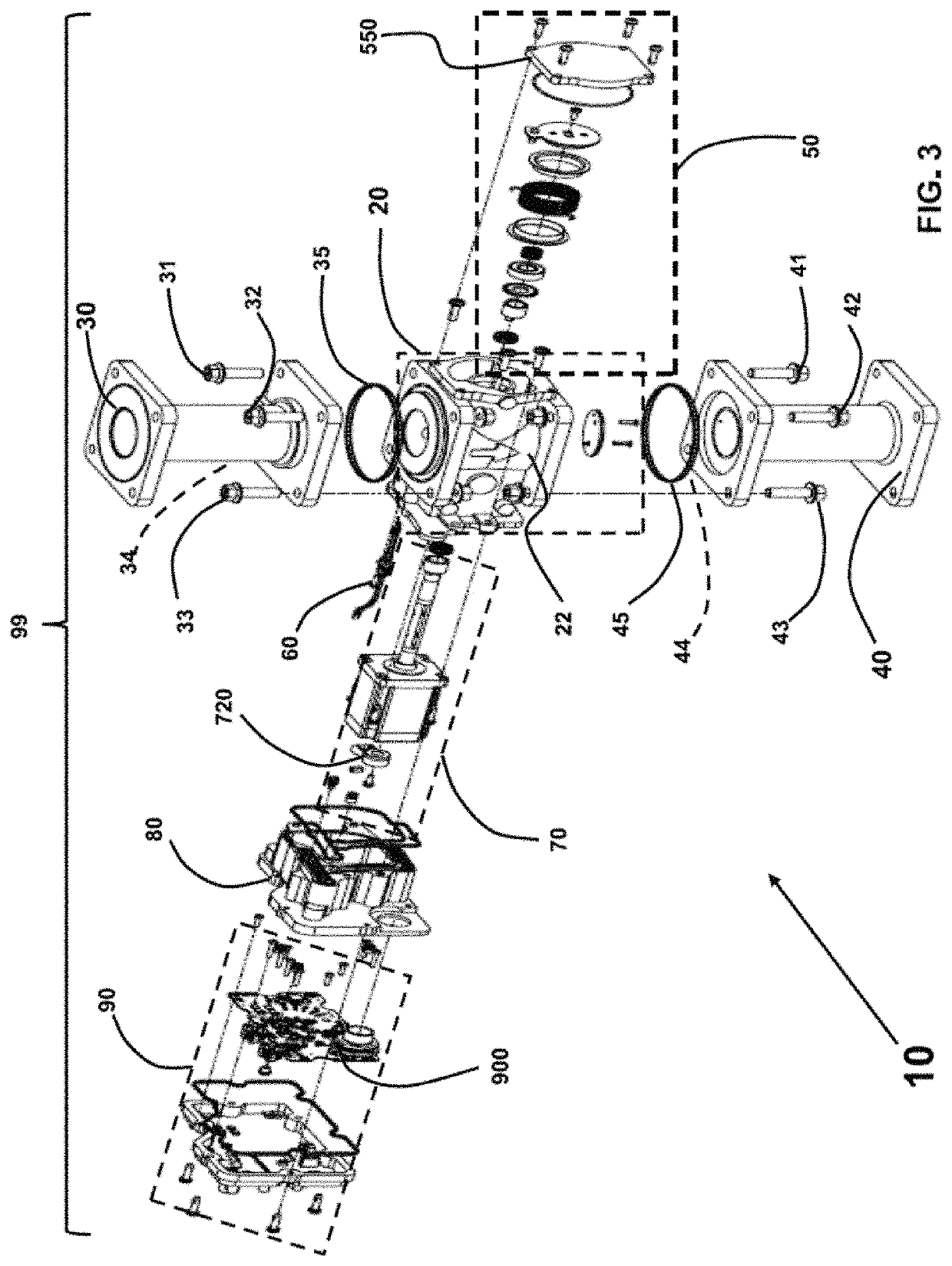
[0013]The resulting combinations of the present invention are not only more versatile and reliable, but they are also able to achieve greater accuracy despite rapidly changing conditions over a larger dynamic power range than has ever been achieved with such a simple system. The various embodiments improve on the related art, including by optimizing reliability, manufacturability, cost, efficiency, ease of use, ease of repair, ease of adaptability, and the like. Although the embodiments referenced below do not provide anything remotely near an exhaustive list, this specification describes select embodiments that are thought to achieve many of the basic elements of the invention.
[0014]In accord with many of the teachings of the present invention, a throttle is provided in a form that is readily adaptable to the power demands of numerous applications and is readily capable of achieving highly accurate setpoint accuracy for controlling gaseous supply flowrates across very large dynamic power ranges in internal combustion engines. Such flowrate control throttles and related fuel systems materially depart from the conventional concepts and designs of the prior art, and in so doing provide many advantages and novel features which are not anticipated, rendered obvious, suggested, or even implied by any of the prior art, either alone or in any obvious combination thereof.
[0015]Through its innovative combination of features and elements, a throttle according to the teachings of the invention is able to consistently and reliably achieve highly accurate mass flow control for various large engine applications, even with non-choked flow. Some of the features and elements that enable that result include the use a unitary block assembly for the throttle, and a fa

Problems solved by technology

This is particularly true in applications where the qu

Method used


Image

  • Mass-flow throttle for large natural gas engines
  • Mass-flow throttle for large natural gas engines
  • Mass-flow throttle for large natural gas engines

Examples


Example

[0037]The following examples are described to illustrate preferred embodiments for carrying out the invention in practice, as well as certain preferred alternative embodiments to the extent they seem particularly illuminating at the time of this writing. In the course of understanding these various descriptions of preferred and alternative embodiments, those of skill in the art will be able to gain a greater understanding of not only the invention but also some of the various ways to make and use the invention and embodiments thereof.

Wording Conventions

[0038]For purposes of these descriptions, a few wording simplifications should be understood as universal, except to the extent otherwise clarified in a particular context either in the specification or in any claims. For purposes of understanding descriptions that may be basic to the invention, the use of the term “or” should be presumed to mean “and / or” unless explicitly indicated to refer to alternatives only, or unless the alterna...


PUM


Abstract

A mass-flow throttle for highly accurate control of gaseous supplies of fuel and/or air to the combustion chambers for a large engine in response to instantaneous demand signals from the engine's engine control module (ECM), especially for large spark-ignited internal combustion engines. With a unitary block assembly and a throttle blade driven by a non-articulated rotary actuator shaft, in combination with control circuitry including multiple pressure sensors as well as sensors for temperature and throttle position, the same basic throttle concepts are suited to be used for both mass-flow gas (MFG) and mass-flow air (MFA) throttles in industrial applications, to achieve highly accurate mass-flow control despite pressure fluctuations while operating in non-choked flow. The throttle, in combination with the sensors and ECM, enable detection of backfire events, with the throttle system further being enabled to take operative measures to prevent damage to the throttle components resulting from a backfire event.

Description

CLAIM OF PRIORITY TO PRIOR APPLICATION[0001]This application claims the benefit of the filing date of U.S. Provisional Application Ser. No. 62 / 812,253, filed on Feb. 28, 2019, entitled “Mass-Flow Throttle for Large Natural Gas Engines,” the entire disclosure of which is hereby incorporated by reference in its entirety.FIELD OF THE INVENTION[0002]The present invention primarily relates to a throttle for large natural gas engines. Particularly, it pertains to a throttle for controlling the mass flow rate to the combustion chambers for large gaseous fuel spark-ignited internal combustion engines, particularly for stationary industrial applications, and more particularly while operating in low pressure non-choked flow, as well as to throttle systems enabling detection of backfire events and protection of throttle components from such backfire events.BACKGROUND[0003]Throttle valves have long been used in large natural gas engines, but existing control strategies tend to be lacking. More ...

Claims


Application Information

Patent Timeline
IPC IPC(8): F02D41/00F02D41/22
CPCF02D41/0002F02D2200/04F02D41/22F02B77/08F02D9/10F02D41/0027F02M21/023F02D9/1065F02D9/1075F02D41/0007F02D19/023Y02T10/30F02M21/0293F02M35/10275F02D2041/1432
Inventor GUGLIELMO, KENNONSANDERS, JUSTIN H.HAMBIDGE, MICHAEL T.WESTERDALE, TIMOTHY J.COLE, JAMES
Owner ECONTROLS
Why Eureka
Try Eureka