
Spinal Stabilization Devices and Methods

Inactive Publication Date: 2009-10-01
WARSAW ORTHOPEDIC INC
View PDF3 Cites 75 Cited by
  • Summary
  • Abstract
  • Description
  • Claims
  • Application Information

AI Technical Summary

Benefits of technology

[0014]The device may additionally or alternatively include a nonosteogenic bioresorbable blocking member sized and configured to be effective for stabilizing a spine against excessive compression. The blocking member is effective for maintaining a medically desired distance between two, adjacent spinous processes when the natural tissue blocking member is positioned between the two spinous processes in the spine of a human patient.

Problems solved by technology

Such stabilizers have the drawback of severely restricting, or even preventing, flexional and extensional movement, thus reducing patient mobility.
In addition, rigid metal constructs may intrude into the adjacent tissue and vasculature, and may require multiple surgeries to install and maintain.
While those materials may provide advantages over rigid metal stabilizers, they may fail to provide either a satisfactory mechanical life or optimal biomechanical performance.
With spinal stenosis, the spinal canal narrows and pinches the spinal cord and nerves, causing pain in the back and legs.
The cushioning discs between the vertebrae also frequently deteriorate, and the facet joints may begin to break down.
The most common symptom of spinal stenosis is pain and difficulty when walking, although numbness, tingling, hot or cold feelings in the legs, and weakness or tiredness may also be experienced.
In extreme cases spinal stenosis can cause cauda equina syndrome, a syndrome characterized by neuromuscular dysfunction that may result in permanent nerve damage.
Medications such as NSAIDS and other anti-inflammatory medications are often used to alleviate pain, although they are not typically effective at addressing the cause of the pain.
While such spacers have found utility when properly made and used, they may not provide the mechanical and immunological properties that are most desired.

Method used


Image

  • Spinal Stabilization Devices and Methods
  • Spinal Stabilization Devices and Methods
  • Spinal Stabilization Devices and Methods

Examples


Embodiment Construction

[0021]For the purposes of promoting an understanding of the principles of the invention, reference will now be made to certain embodiments thereof and specific language will be used to describe the same. It will nevertheless be understood that no limitation of the scope of the invention is thereby intended, such alterations and further modifications of the disclosed embodiments being contemplated as would normally occur to one skilled in the art to which the invention relates.

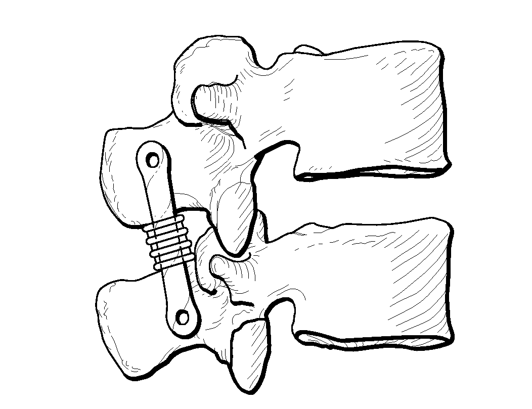
[0022]As indicated above, one aspect of the present invention relates to stabilizers for stabilizing a spine, wherein the stabilizers comprise, consist of, or consist essentially of a bioresorbable, nonosteogenic, and / or biointegrable material such as natural tissue. In some embodiments the stabilizers may be used to stabilize a single vertebra, and thus to protect against excessive and / or undesired motion of that segment. In other embodiments the stabilizers may be used to hold two to more spinal motion segmen...


PUM


Abstract

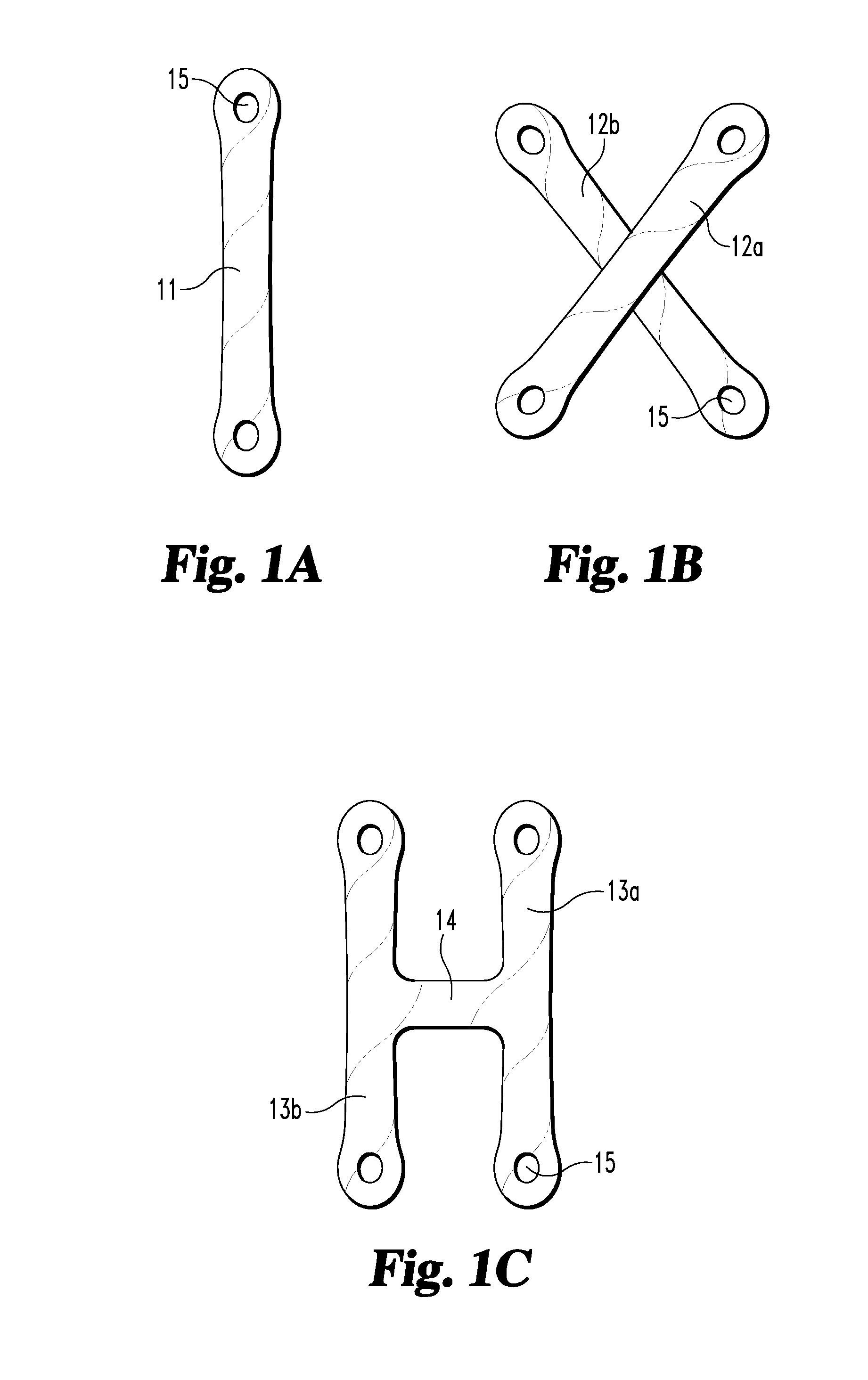
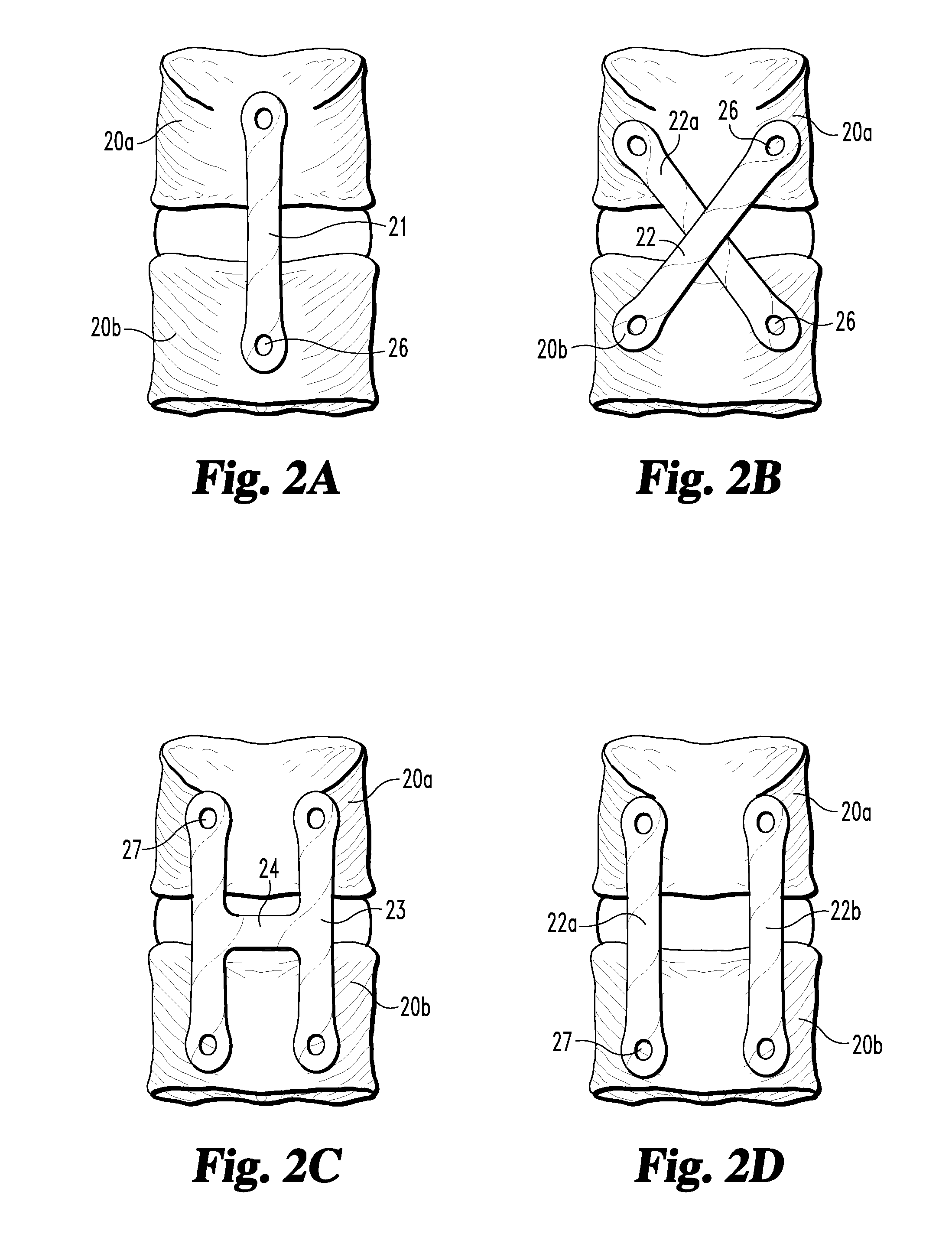
A device and method for stabilizing a spine utilizes one or more stabilization members made of, or including, a bioresorbable and / or biointegrable material such as natural tissue or a bioresorbable polymer. The stabilization member(s) may be elastic, and may secure one or more spinal motion segments in a manner effective to reduce the range of flexion and / or extension of the spinal motion segments. The stabilization member may include one or more elongate straps of nonosteogenic natural tissue, each of which may be secured to the spine using fasteners such as bone screws or tacks. The stabilization device may include a blocking member sized and configured to be effective for maintaining a medically desirable distance between adjacent spinous processes in the spine of a medical patient.

Description

FIELD OF THE INVENTION[0001]The present invention relates generally to devices and methods for stabilizing a spine, and more particularly to devices and methods for stabilizing a spine against excessive extension or compression.BACKGROUND OF THE INVENTION[0002]Intervertebral stabilizers are known to be used to prevent excessive flexion or extension motion of the spinal column. The most aggressive stabilizers are metal plates or rods that are fixed to the vertebrae along the affected region to completely immobilize the vertebrae. Such stabilizers have the drawback of severely restricting, or even preventing, flexional and extensional movement, thus reducing patient mobility. In addition, rigid metal constructs may intrude into the adjacent tissue and vasculature, and may require multiple surgeries to install and maintain.[0003]More recently, flexible stabilizers have been developed to overcome disadvantages of the prior art metal stabilizers. For example, U.S. Pat. No. 6,652,585 to L...

Claims


Application Information

Patent Timeline
IPC IPC(8): A61B17/70
CPCA61B17/7059A61B2017/00004A61B17/7062
Inventor LEHUEC, JEAN CHARLESMATHEWS, HALLETT H.LIU, MINGYAN
Owner WARSAW ORTHOPEDIC INC
Learn More