
Stud with lengthwise indented grooves, and with intervening planar surfaces, and method

Inactive Publication Date: 2009-10-08
BODNAR ERNEST R
View PDF5 Cites 38 Cited by
  • Summary
  • Abstract
  • Description
  • Claims
  • Application Information

AI Technical Summary

Benefits of technology

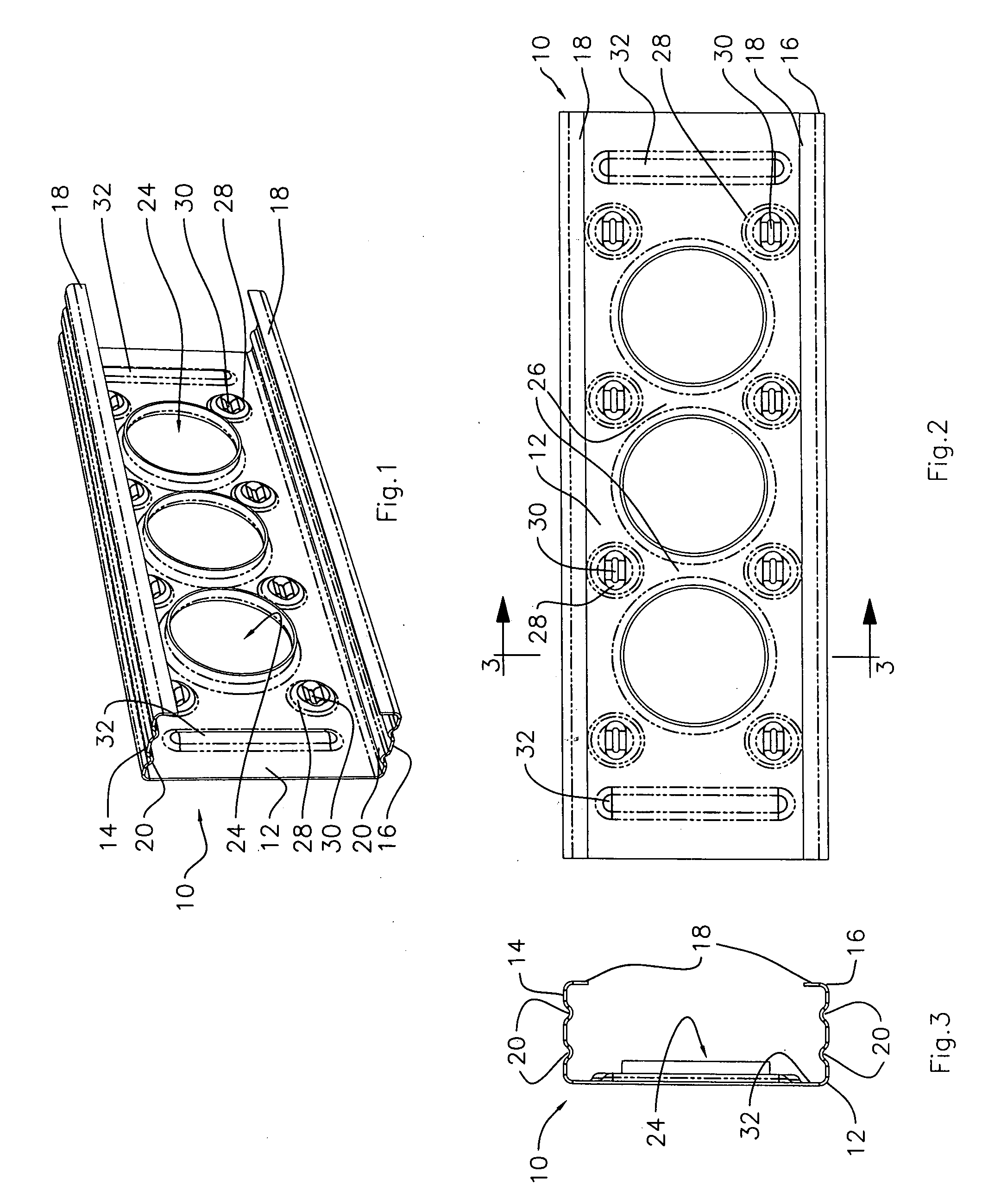
[0018]The invention further seeks to provide a steel member as described, which is particularly suited for use in the supporting of dry wall partitions, and may incorporate a cross brace with a snap-in engagement. This type of stud does not have the problem of heat transfer since the partition walls are usually erected inside the building, dividing up the space into separate rooms. They will not necessarily use the complex web openings and ribs of the other embodiments. Such studs may be made of ultra light weight, thin gauge steel. For this purpouse the studs have flanges which are formed with numerous point-like depressions or dimple-like indentations. These add stiffness and also provide pints for easy secure insertion of screw fastenings.
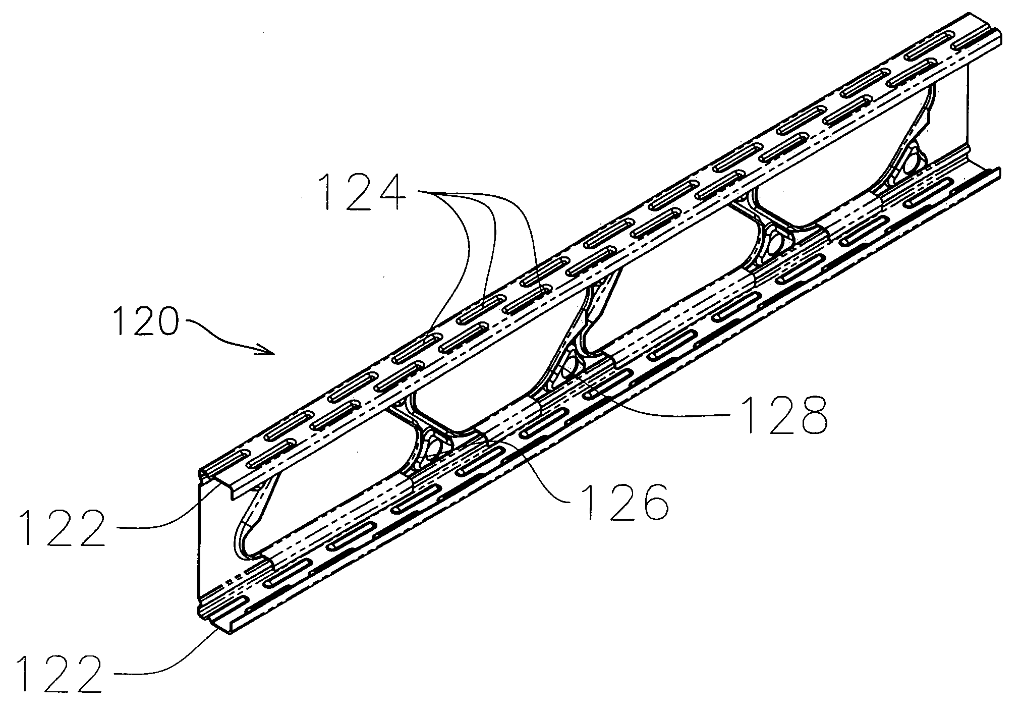
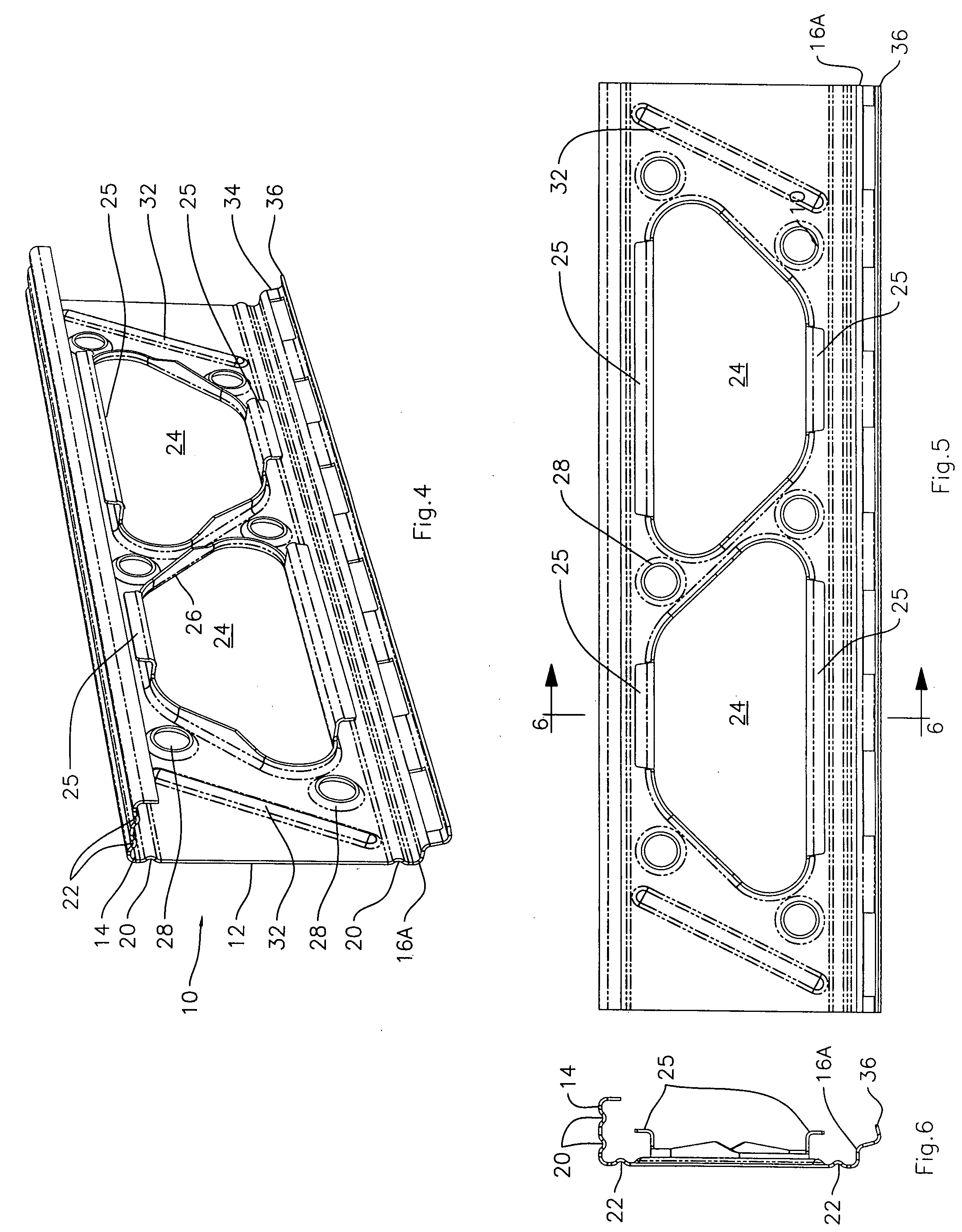
[0020]The invention further seeks to provide a steel member as described with diagonal ribs between the web openings, and with depressions formed in the web at each end of each rib, indented from said outside to said inside surfaces and, rib openings formed in the depressions to reduce heat transfer.

Problems solved by technology

Wood is a relatively poor heat transfer medium.
Metal studs having solid webs however, do create a heat loss transfer path through the exterior wall or other structure.
This results in cold patches along the lines of the studs.
However this did not overcome the heat transfer problem.
Corrugations do not provide a surface suitable for attachment of structure such as wall panels.
If screws are secured through the panel into the metal the screws may penetrate the metal in a random fashion, and cause unequal pressure points in the panel, and may damage the panel.
A more serious problem with corrugations in a stud, is that the manufacturing process by which corrugations are folded into the sheet metal, causes the metal to be drawn from the edges in towards the centre of the strip.
This means that it is difficult to produce a stud as an end product, which has a definite preset width.
Also the stud so produced will use a greater quantity of steel, making it more costly.

Method used


Image

  • Stud with lengthwise indented grooves, and with intervening planar surfaces, and method
  • Stud with lengthwise indented grooves, and with intervening planar surfaces, and method
  • Stud with lengthwise indented grooves, and with intervening planar surfaces, and method

Examples


Embodiment Construction

[0054]As already described the invention provides sheet metal structural members referred to herein generically as studs, suitable for use in erecting various structures, walls, floors, roofs, and the like and also internal partition walls. The invention also provides sheet metal studs suitable for use in reinforcement of thin-shell concrete panels which are widely used in completing walls, in particular. Such thin-shell structures can also form floors, roofs and the like, and can also serve as shuttering or form work for pouring concrete, such as columns and beams, and even flooring and concrete partitions. Such thin-shell panels, when used as shuttering, may be left in place, thus avoiding the need for removing and repositioning shuttering or form work, many times over. The invention also provides a method of making such studs.

[0055]Referring to FIG. 1 it will be seen that the invention is there illustrated in the form of a stud (10), formed of sheet metal, in this case steel. The...


PUM

PropertyMeasurementUnit
Lengthaaaaaaaaaa
Lengthaaaaaaaaaa
Lengthaaaaaaaaaa

Abstract

A steel stud member for use in supporting structures and having reduced thickness as compared with conventional studs, and having a web having side edges, flanges on the side edges, formed at angles to the web, the web and the flanges enclosing inside surfaces, and having outside surfaces for mounting structure, and plurality of narrow indented longitudinal grooves formed in the flanges, and in the web, indented inwardly from the outside to the inside of the flanges, providing greater load bearing capacity for a given gauge of steel. Also disclosed is a method of making such a steel member.In another embodiment the flanges are indented with a plurality of separate dimples

Description

[0001]This application is a Continuation in Part of application Ser. No. 11 / 652,073 filed, Jan. 11 2007, Title, STUD WITH LENGTHWISE INDENTED RIBS AND METHOD, Inventor Ernest R Bodnar, which turn claimed priority of U.S. Provisional Application Ser. No. 60 / 759,068 Filed Jan. 11 2006 Title STUD WITH LENGTHWISE INDENTED RIBS AND METHOD, inventor Ernest R Bodnar.FIELD OF THE INVENTION[0002]The invention relates to steel studs or structural members formed with edge formations, with planar edge flanges and indents located between planar portions of the edge flanges. The stud indents may be grooves or dimpled surfaces. In a particular preferred form the studs are formed with web main openings and edge formations along at least one side of the openings formed with at least two indented parallel spaced apart grooves in each said edge flange.BACKGROUND OF THE INVENTION[0003]Steel studs of a wide variety have been proposed for erecting structures. Usually such studs are used to replace wooden...

Claims


Application Information

Patent Timeline
IPC IPC(8): E04C3/04B21D47/01
CPCE04C3/09Y10T29/49631E04C2003/0473
Inventor BODNAR, ERNEST R.
Owner BODNAR ERNEST R
Learn More