System for detecting one or more predetermined optically derivable characteristics of a sample

a sample and optical derivation technology, applied in the field of system for detecting one or more predetermined optical derivation characteristics of a sample, can solve the problems of inability to accurately detect the output of such moisture meters using sophisticated and expensive near infrared technology, inability to use in the field, and inability to accurately detect the output of such moisture meters

Active Publication Date: 2009-10-08
ROSEWOOD RES
View PDF11 Cites 11 Cited by
  • Summary
  • Abstract
  • Description
  • Claims
  • Application Information

AI Technical Summary

Problems solved by technology

Portable moisture meters suitable for in-field use are known but there is considerable difficulty in aligning the output from such moisture meters with laboratory type equipment using sophisticated and expensive near infrared technology which has been developed for use at grain receival points.
Relatively expensive equipment is known for use in laboratory and receival conditions to measure the moisture in grain with sufficient accuracy for trading.
A critical limitation pointed out by the present inventors is that equipment available on the market is essentially laboratory scale equipment which is capable of highly accurate performance but is essentially not suitable for field use.
Furthermore, and most importantly, it is relatively expensive equipment particularly because of the expensive and careful alignment steps needed for each and every instrument so that the output data from all the instruments is consistent.
That is, considerable effort and expense is expended in ensuring that all the instruments will provide consistent results for a given sample.
If the grain has excessive moisture, it may be rejected at great economic loss to the farmer or if the moisture is somewhat high then the price will be downgraded.

Method used


Image

  • System for detecting one or more predetermined optically derivable characteristics of a sample
  • System for detecting one or more predetermined optically derivable characteristics of a sample
  • System for detecting one or more predetermined optically derivable characteristics of a sample

Examples


Embodiment Construction

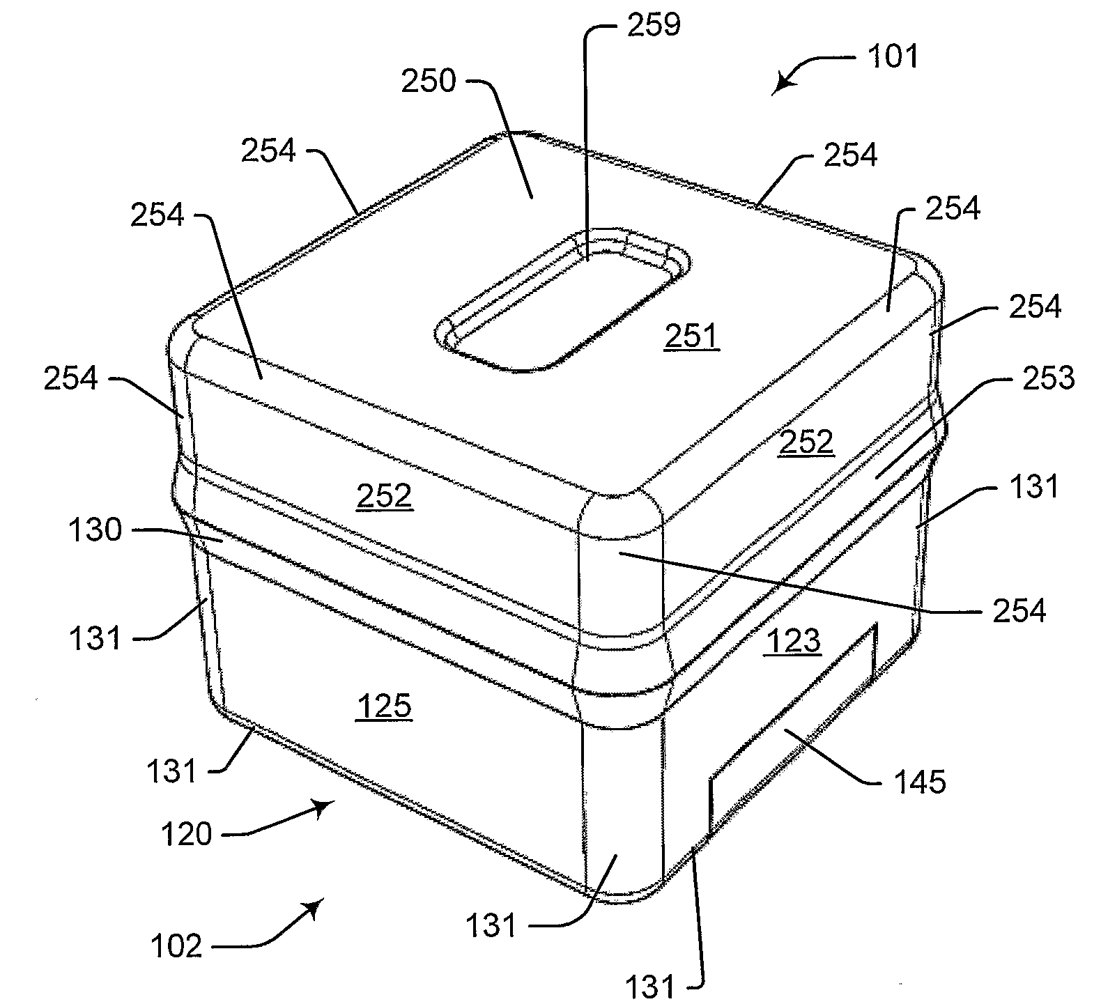
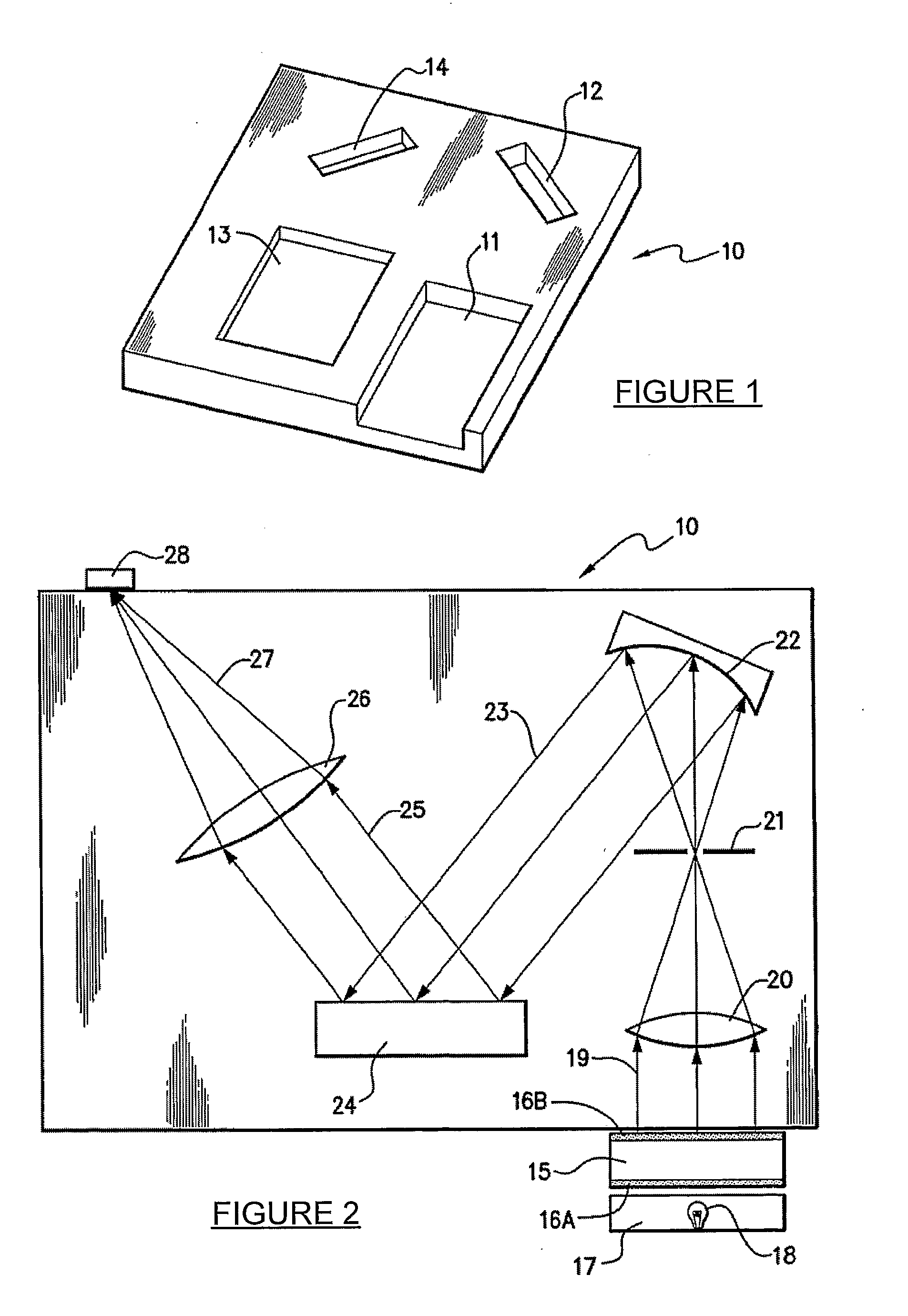
[0116]FIG. 1 shows a thick base plate 10 of a stable plastic material such as PVC which is typically 12 mm thick. It has deep mounting recesses 11 to 14 respectively for an optical barrel, a concave mirror, a reflection diffraction grating, and a focusing lens. The base plate 10 encapsulates these components by placement of a top plate 10, which is substantially a minor image of the base plate, on top of the base plate.

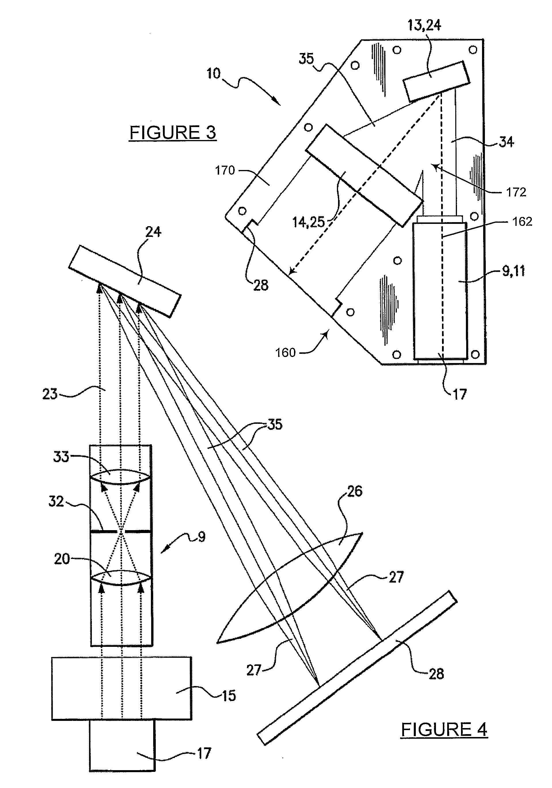
[0117]Referring now to FIG. 2, more detail is shown schematically of the components in the optical system. The apparatus has a sample container 15 mounted adjacent to the base plate 8 and adapted to contain a sample such as grain. A light source 17 having a halogen bulb 18 is mounted adjacent to the sample container 15 so that light from the bulb 18 passes through an inlet window 16A, is transmitted through the sample, and out through an outlet window 16B to form a beam 19 affected by the sample. This beam is incident on the optical barrel which comprises a lens 20 an...


PUM

PropertyMeasurementUnit
volumeaaaaaaaaaa
thicknessaaaaaaaaaa
thickaaaaaaaaaa

Abstract

A field use optical grain characterising system (101) includes a generally rectangular prismatic composite body (102) that defines a component cavity (103). A substantially vertical elongate channel (104) extends within cavity (103) for housing a grain sample (not shown). An electromagnetic radiation source, in the form of a 12 Volt halogen lamp (105), is disposed within cavity (103.) for directing NIR light into channel (104). An optical detection system (107) is disposed within cavity (103) for sensing selected light emerging from channel (104) and for providing a sensor signal. A processor, which is included within detection system (107), is also disposed within cavity (103) and is responsive to the sensor signal for providing data indicative of a characteristic parameter of the grain sample. A display device, in the form of a 5.7-inch touch screen LCD display (108), is connected with body (102) for selectively presenting the data.

Description

FIELD OF THE INVENTION[0001]The present invention relates to a system for detecting one or more predetermined optically derivable characteristics of a sample.[0002]The invention has been primarily developed as a portable optical grain characterising system and will be described hereinafter with reference to this application. However, it will be appreciated that the invention is not limited to this particular field of use and, for example, may be used for analysing other products that are responsive to illumination by light for measurably varying a characteristic of the light that allows a parameter to be monitored.BACKGROUND OF THE INVENTION[0003]Any discussion of the prior art throughout the specification should in no way be considered as an admission that such prior art is widely known or forms part of common general knowledge in the field.[0004]It is known that a product such as grain can be monitored by an optical methodology to determine, for example, the percentage of moisture...

Claims


Application Information

Patent Timeline
Patent Type & Authority Applications(United States)
IPC IPC(8): G01J1/42G01N21/01
CPCG01N21/3563G01N21/359G01N2201/0221G01N2021/8592G01N33/10
Inventor KALITSIS, JOHNWESLEY, IAN JOHNCARPENTER, WILLIAM
Owner ROSEWOOD RES
Why Eureka
Try Eureka