
Lifting Cart

a technology for lifting carts and lifting wheels, applied in the field of lifting carts, can solve the problems of inconvenient use, goods are likely to fall off due to shake, and can be lifted to the top,

Inactive Publication Date: 2009-10-08
MAW HUNG INDAL
View PDF9 Cites 39 Cited by
  • Summary
  • Abstract
  • Description
  • Claims
  • Application Information

AI Technical Summary

Benefits of technology

[0007]The primary objective of the present invention is to provide a lift cart which can be adjusted in height, position, and rotation angle during disassembly of the engine.
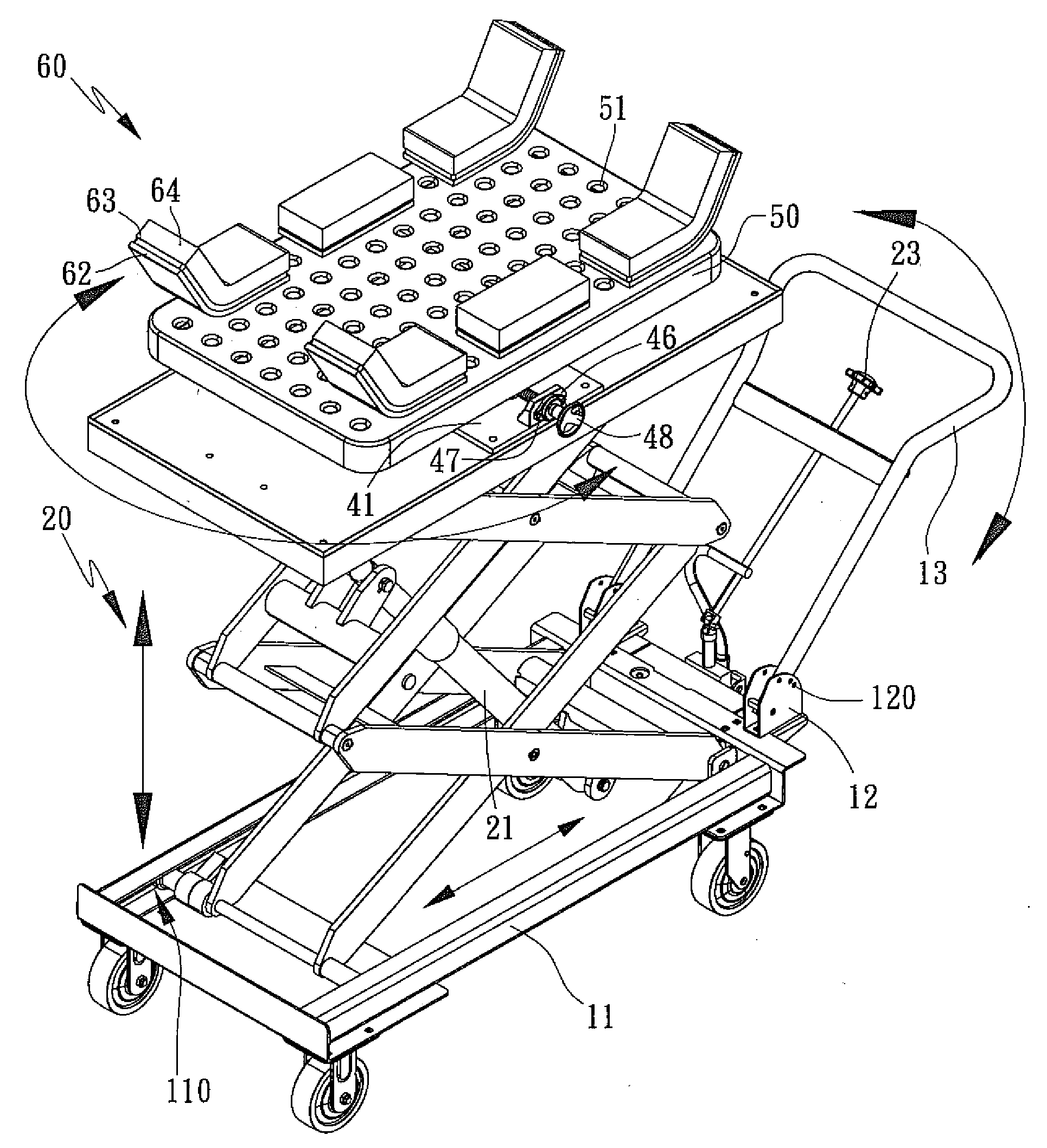
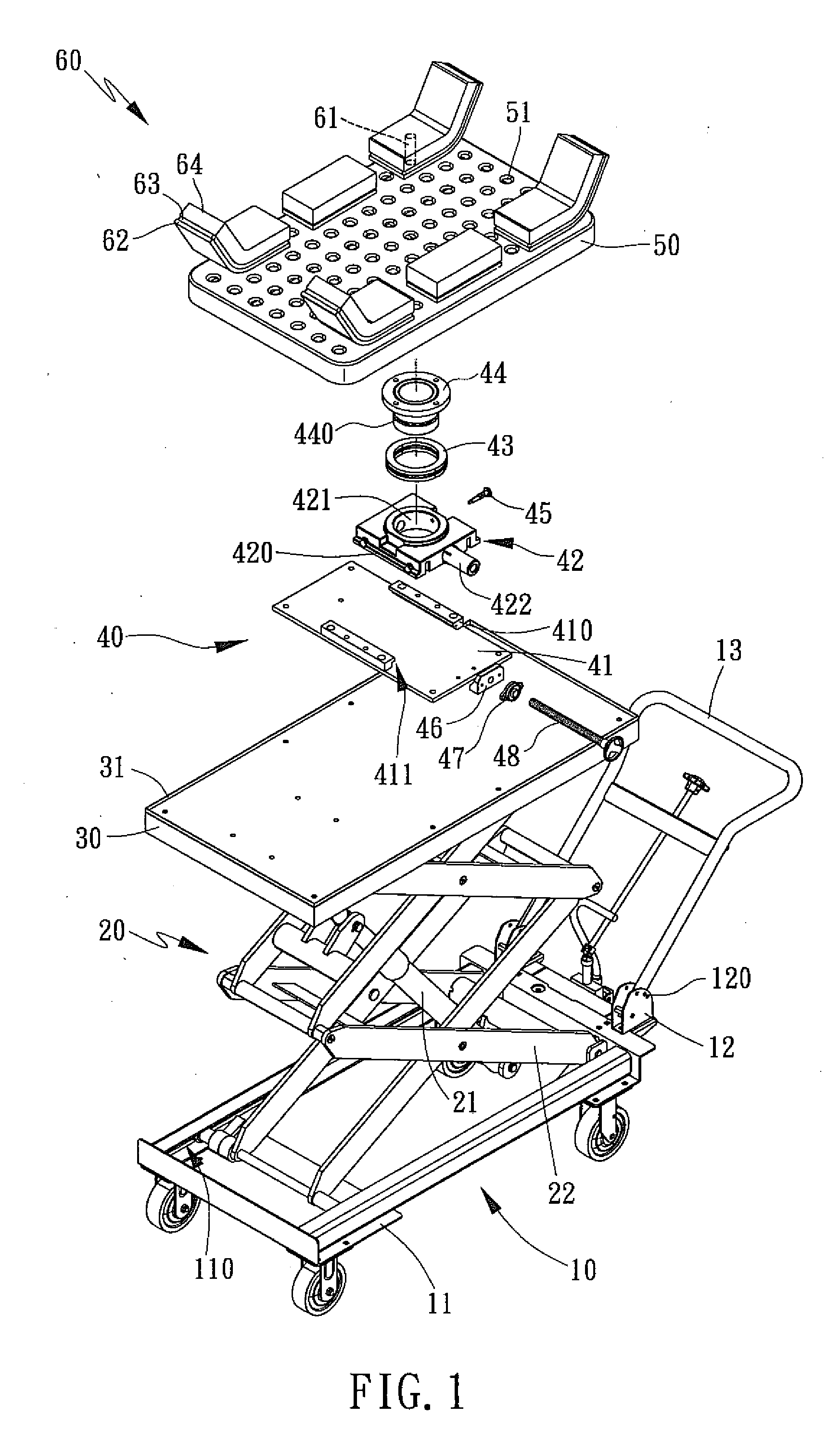
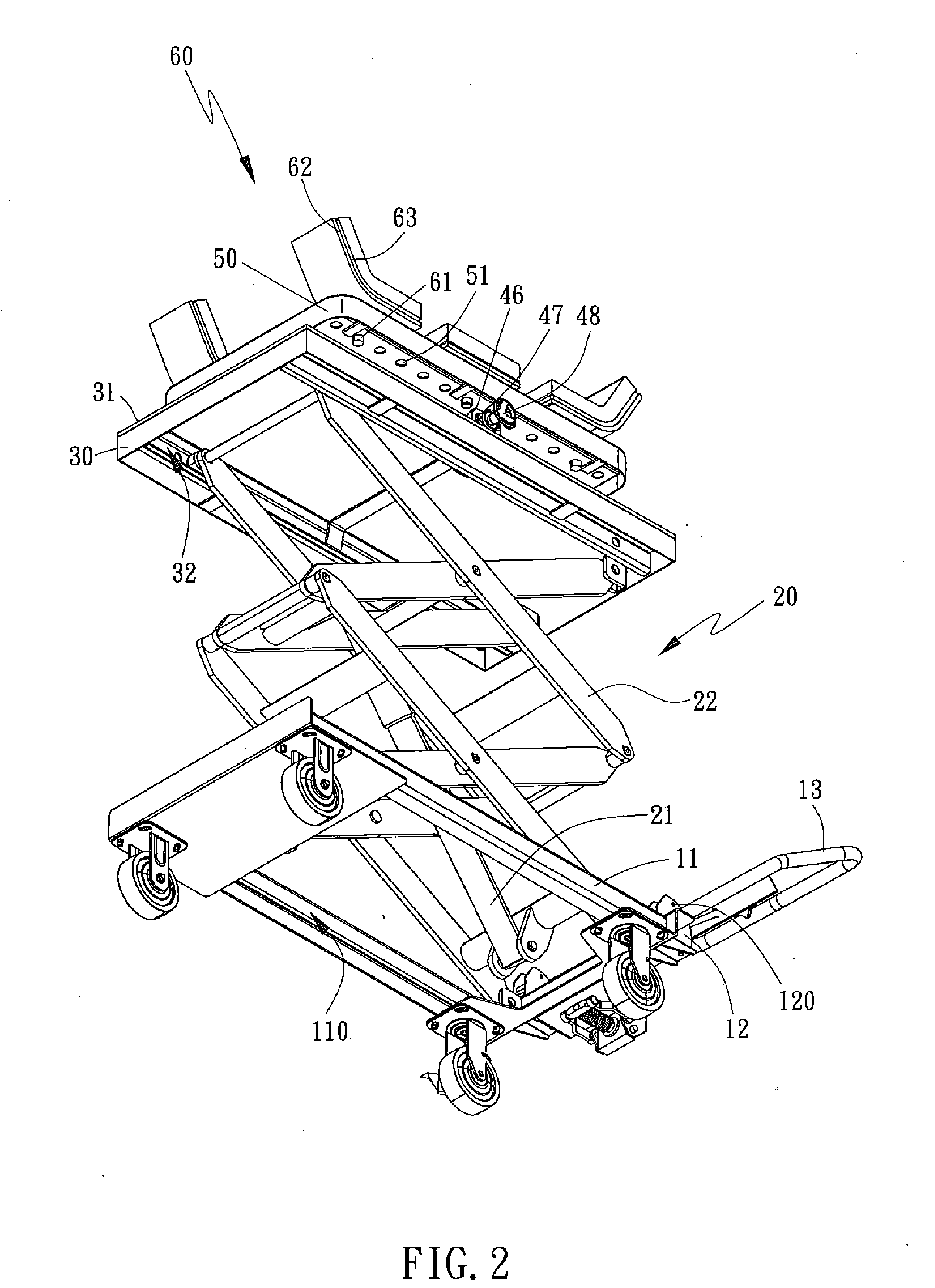
[0009]The above-mentioned oil pressure lifting device is connected to the moving base, which allows the maintenance man to make the height adjustment during disassembly of the engine. In addition, the maintenance man can make the back and forth, and rotation angle adjustment during the maintenance of the engine by cooperating with the moving block, the turning member and the screw of the adjusting device.
[0010]The second objective of the present invention is to provide a lift cart. Each carrying structure comprises an inserting member, a vibration absorbing member, a jointing member and an anti-slip member, which are integrally formed as one-piece structure. The carrying structure is inserted in the supporting plate, such that the engine placed on the carrying structures is unlikely to be fallen off, so as to achieve the object of high safety of maintenance. The inserting member is made of a hard material, such as steel and iron. The vibration absorbing member is made of a material, such as sponge and plastic. The jointing member is made of the hard material, such as steel and iron. The anti-slip member has a granular surface. The above-mentioned structures of each carrying structure can be integrally formed as one-piece structure. In addition, the carrying structure can be designed to be an inclined or a planar structure.

Problems solved by technology

However, such a cart can only be used to carry ordinary goods and the height to which the goods can be lifted is very limited, so it is inconvenient to use.
Such a lift cart can lift the platform, but when in use, the goods are likely to be fallen of due to shake.
As a result, the goods are likely to be broken and the maintenance man is likely to be injured.

Method used


Image

  • Lifting Cart
  • Lifting Cart
  • Lifting Cart

Examples


Embodiment Construction

[0016]Referring to FIGS. 1-4, a lift cart in accordance with the present invention is used for car engine maintenance and comprises a moving base 10 for mounting an oil pressure lifting device 20. One end of the oil pressure lifting device 20 is provided with a platform 30 having a rotatable adjusting device 40 which is adjustable back and forth. The adjusting device 40 is provided with a supporting plate 50, and a plurality of carrying structures 60 for carrying different sized engine is positioned on the supporting plate 50. Such arrangements allow the maintenance man to make the height, back and forth, and rotation angle adjustment during disassembly of the engine.

[0017]The moving base 10 comprises a rectangular frame 11. Both long sides of the frame 1 are defined with a first sliding groove 110, respectively, and both ends of one of the short sides of the frame 1 are provided with a U-shaped supporting seat 12. Both sides of each supporting seat 12 are defined with a plurality o...


PUM


Abstract

A lift cart is used for car engine maintenance and comprises a moving base for mounting an oil pressure lifting device. One end of the oil pressure lifting device is provided with a platform having a rotatable adjusting device which is adjustable back and forth. The adjusting device is provided with a supporting plate, and a plurality of carrying structures for carrying different sized engine is positioned on the supporting plate. Such arrangements allow the maintenance man to make the height, back and forth, and rotation angle adjustment during disassembly of the engine.

Description

BACKGROUND OF THE INVENTION[0001]1. Field of the Invention[0002]The present invention relates to a lift cart used for car engine maintenance, and more particularly to a lift cart which can be adjusted in height, position, and rotation angle during disassembly of the engine.[0003]2. Description of the Prior Art[0004]A cart with a lift structure disclosed in TW Pat. serial number 087207581 is a hand truck which can be lifted for carrying goods, which comprises a base, a connecting rod, a carrying rack, two follower rods, an extension rod and a driving rod. The base is a L-shaped structure the front end of which is lower than the rear end, and the carrying rack is mounted on the base for carrying goods. The follower rods, the extension rod and the driving rod are used as a lever to push the carrying rack to pivot forward into a lifting mode or to discharge the goods. However, such a cart can only be used to carry ordinary goods and the height to which the goods can be lifted is very li...

Claims


Application Information

Patent Timeline
IPC IPC(8): B66F9/22F16M11/38
CPCB66F7/08B66F7/0666
Inventor LIN, CHI-TING
Owner MAW HUNG INDAL
Learn More