Knotter for a Baler

Active Publication Date: 2009-10-08
BLUE LEAF I P
View PDF0 Cites 20 Cited by
  • Summary
  • Abstract
  • Description
  • Claims
  • Application Information

AI Technical Summary

Benefits of technology

[0012]As the bill hook rotates to complete the formation of the second knot, the two runs of twine slide along the edge of the twine finger. By providing an obstruction along this edge to resist movement of the twines, the section of the twine runs that includes the second knot to be under higher tensio

Problems solved by technology

While it may generally be stated that increased density in such bales is a highly desirable objective, obtaining that goal has in many respects been thwarted because of the limitations of conventional wire and twine tying mechanisms.
Beyond a certain level of tension in the wire or twine strands, the mechanisms experience difficulty in holding on to the strands and manipulating the same through the various motions involved in tying the opposite ends of the strands into a satisfactory knot or other type of connection.
Moreover, the strands thems

Method used


Image

  • Knotter for a Baler
  • Knotter for a Baler
  • Knotter for a Baler

Examples


Embodiment Construction

[0023]In the description which follows and in certain passages already set forth, the principles of the present invention will be described in terms of “twine” and “knots” formed in such twine. However, it is to be recognized that such principles extend to wire and twisted junctions of wire as well as twine and knots. The claims should be interpreted accordingly.

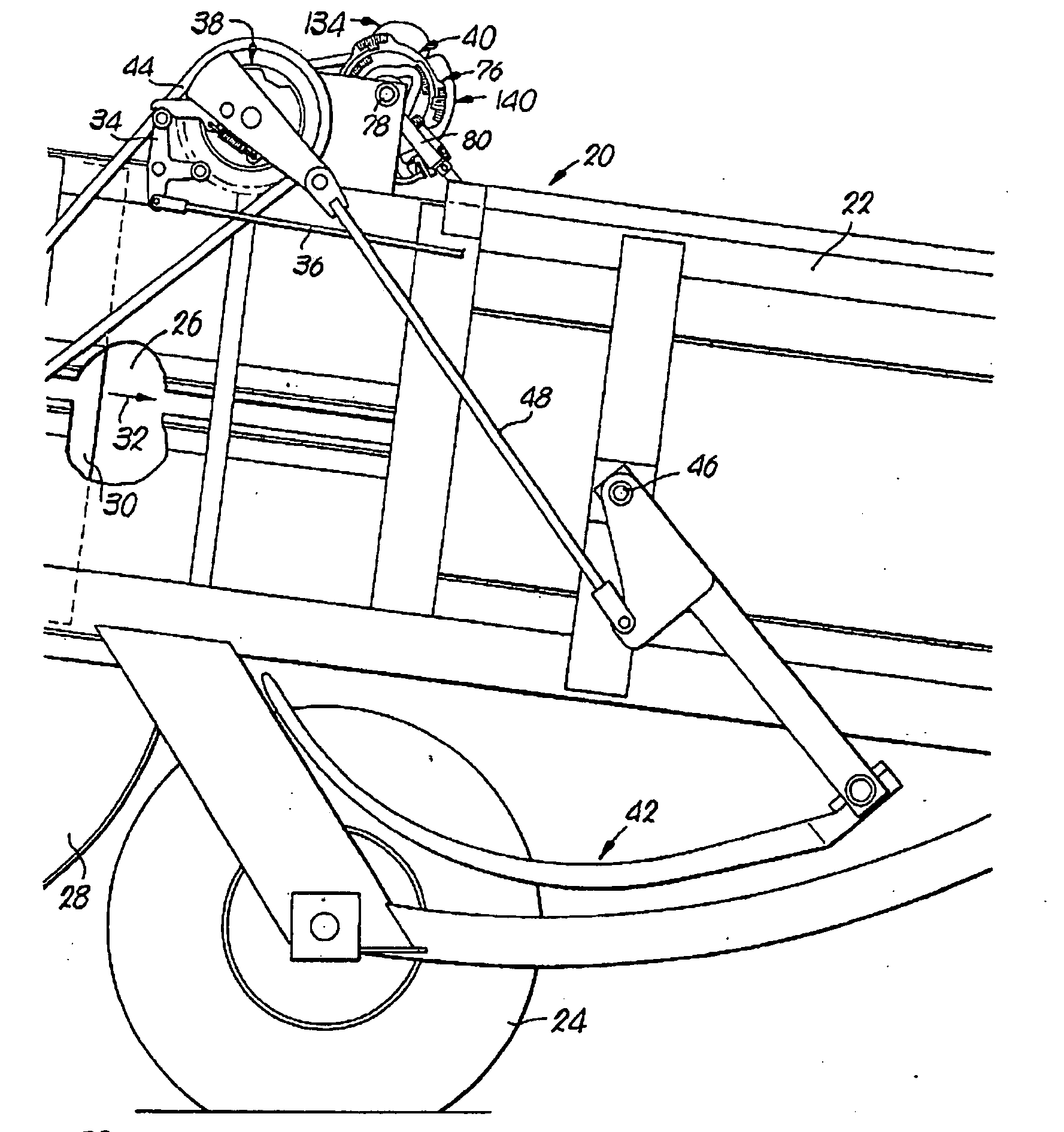
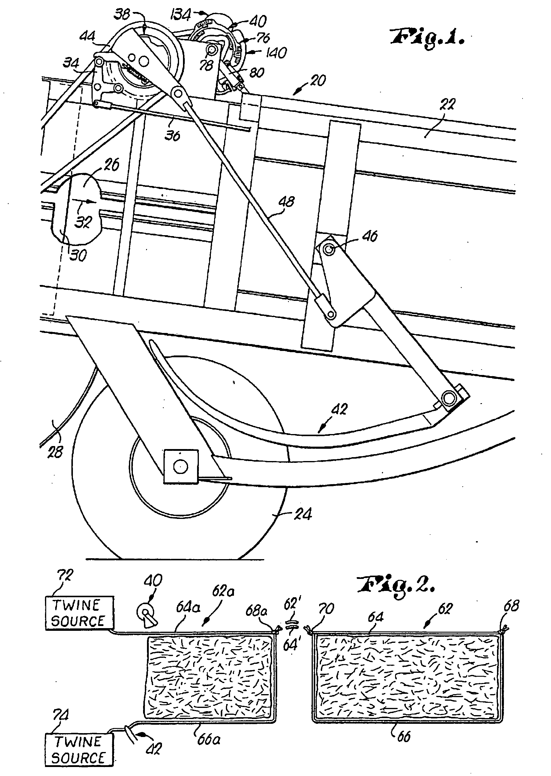
[0024]The baler 20 illustrated in FIG. 1 has a rectangular bale case 22 that happens to be supported for over-the-ground travel by one or more ground wheels 24. The bale case 22 defines a bale chamber 26 that happens to be loaded through a curved duct 28 approaching the case 22 from the bottom thereof. A plunger 30 reciprocates within the bale case 22 to intermittently pack fresh charges of material from the duct 28 rearwardly in the chamber 26 in the direction of the arrow 32. When the bale reaches a predetermined size, a trigger 34 is pulled by a rod 36 connected to a suitable bale length sensor (not shown) to engage a dog...


PUM


Abstract

A knotter had a twine holder, a bill hook, an arm carrying a crotch and a cutter and a twine finger operated by a drive mechanism to form two knots consecutively, the first to tie together two runs of twine passed around a completed bale and the second to tie together two runs of twine drawn from respective supply rolls for the commencement of the next bale. The twine holder serves to grip the two runs of twine drawn from the supply rolls throughout the formation of the two knots. The bill hook serves to knot the runs of twine gripped by the holder. The cutter serves to sever the runs of twine between the holder and the bill hook. The crotch pushes the twine runs off the bill hook during the completion of each knot. The twine finger is pivotably mounted on the opposite side of the bill hook from the twine holder to bring the sections of the runs of twine to be knotted within the reach of the bill hook. In the invention, an edge of the twine finger contacting the runs of twine as the knots are pushed off the bill hook by the crotch comprises an obstruction to resist movement of the runs of twine in a direction transverse to their length.

Description

[0001]This invention relates to a knotter for binding bales of harvested crop material or other substances so that the bales may be handled, stored or otherwise manipulated without breaking apart.BACKGROUND OF THE INVENTION[0002]Bales are often prepared under conditions of substantial pressure so that the finished product is considerably more dense than the loose material from which it is made.[0003]While it may generally be stated that increased density in such bales is a highly desirable objective, obtaining that goal has in many respects been thwarted because of the limitations of conventional wire and twine tying mechanisms. Beyond a certain level of tension in the wire or twine strands, the mechanisms experience difficulty in holding on to the strands and manipulating the same through the various motions involved in tying the opposite ends of the strands into a satisfactory knot or other type of connection. Moreover, the strands themselves can only withstand certain levels of t...

Claims


Application Information

Patent Timeline
IPC IPC(8): A01D59/04
CPCA01F15/145
Inventor EYLENBOSCH, KRISSCHOONHEERE, MARNIX J.
Owner BLUE LEAF I P
Why Eureka
Try Eureka