High frequency magnetic field coil and magnetic resonance imaging apparatus with the same

a magnetic field coil and high frequency technology, applied in the field of high frequency magnetic field coils and magnetic resonance imaging apparatuses with the same frequency, can solve the problems of low sensitivity of double tunable rf coils compared with coils having a single resonance frequency, interference, etc., and achieve a slight sensitivity reduction

Inactive Publication Date: 2009-10-08
HITACHI LTD
View PDF24 Cites 53 Cited by
  • Summary
  • Abstract
  • Description
  • Claims
  • Application Information

AI Technical Summary

Benefits of technology

[0011]According to the present invention, an RF coil that is used in imaging in which MR signals of the two kinds of nuclides are designated as objects to be detected in multinuclear imaging and that does not need exchange and adjustment of itself for the each object nuclide also with slight lowering in sensitivity can be obtained.

Problems solved by technology

However, when using a different RF coil for every nuclide that is an object to be detected, time and manpower are necessary to exchange the RF coil, and there is a possibility that a shift of a point of the subject etc. may occur at the time of exchange.
On the other hand, in a coil that uses a characteristic of a birdcage type RF coil, interference takes place in the case where values of resonance frequencies are near to each other.
Moreover, the double tunable RF coil has a low sensitivity compared with the coil having a single resonance frequency.
A coil that is adjusted by a distance to the RF shield not only needs to be adjusted each time the nuclide that is the object to be detected is changed but also may require a large-sized complex adjustment mechanism.

Method used


Image

  • High frequency magnetic field coil and magnetic resonance imaging apparatus with the same
  • High frequency magnetic field coil and magnetic resonance imaging apparatus with the same
  • High frequency magnetic field coil and magnetic resonance imaging apparatus with the same

Examples


first embodiment

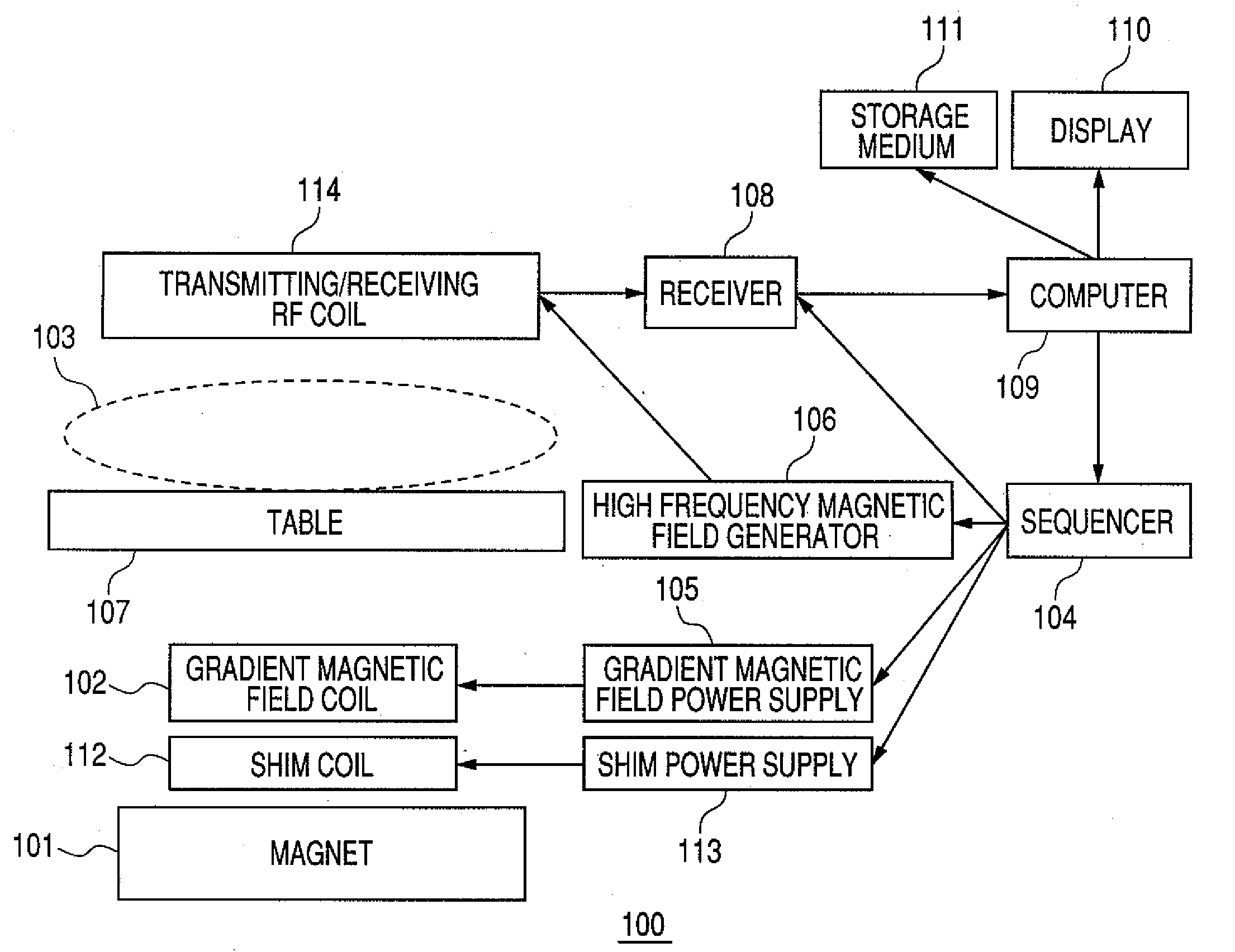
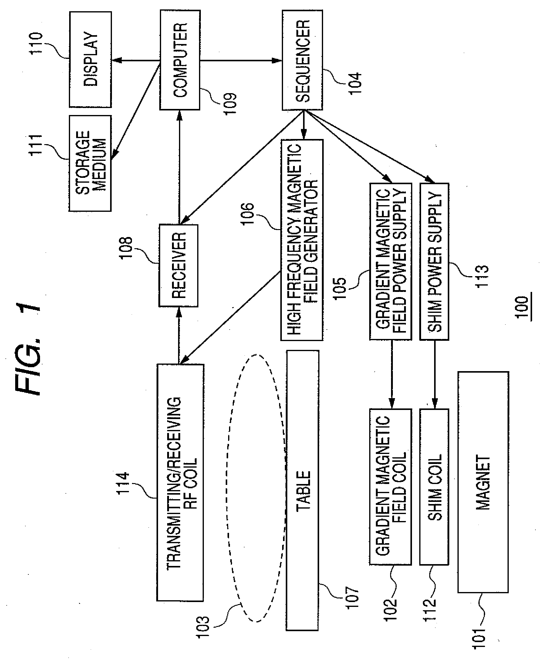
[0029]Hereafter, a first embodiment of the present invention will be described. First, an entire configuration of an MRI apparatus of the first embodiment will be explained. FIG. 1 is a block diagram of an MRI apparatus 100 of this embodiment. As shown in this figure, the MRI apparatus 100 of this embodiment comprises a magnet 101 for generating a static magnetic field, a coil 102 for generating a gradient magnetic field, a shim coil 112 for adjusting a uniformity coefficient of the static magnetic field, a sequencer 104, a transmitting / receiving RF coil 114 for generating a high frequency magnetic field, and a table 107 on which a subject 103 is placed and held. The gradient magnetic field coil 102 and the shim coil 112 are connected to a gradient magnetic field power supply 105 and a shim power supply 113, respectively. The transmitting / receiving RF coil 114 is connected to a high frequency magnetic field generator 106 and a receiver 108. The sequencer 104 sends commands to the gr...

second embodiment

[0044]Next, a second embodiment to which the present invention is applied will be described. A configuration of the transmitting / receiving RF coil 114 of this embodiment is fundamentally the same as that of the first embodiment. However, in this embodiment, the MRI apparatus side has a configuration that controls changeover of the switch of the transmitting / receiving RF coil 114. Below, this embodiment will be described, mainly focusing on its configuration different from that of a counterpart of the first embodiment. Any circuit, component, or the like that has the same configuration as that of the first embodiment is given the same reference numeral.

[0045]FIG. 5 is a block diagram of an MRI apparatus 100′ of this embodiment. As shown in this figure, the MRI apparatus 100′ of this embodiment has fundamentally the same configuration as that of the MRI apparatus 100 of the first embodiment. However, a configuration of a computer 109′ is different. The computer 109′ of this embodiment...

first example

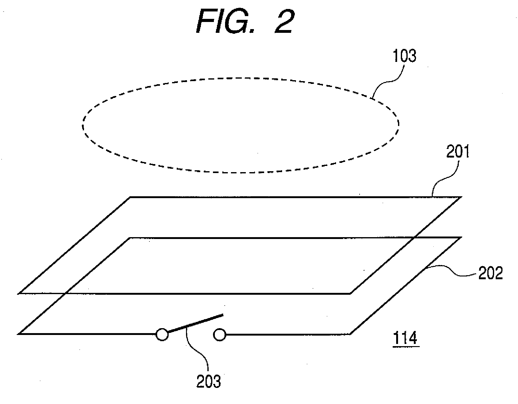
[0057]Hereafter, an example whereby feasibility of the frequency shift (changeover) of a transmitting / receiving RF coil 114 of the first embodiment was verified will be described. In the first example, as the first coil 201 of the transmitting / receiving RF coil 114-1, a multipurpose coil that is normally used in clinical applications is used. In this example, simulation of a frequency characteristic of the first coil 201 was performed in each of the case where the switch 203 was maintained in ON state and the case where the switch 203 was maintained in OFF state, respectively. Specifically, the value of the impedance of the first coil 201 when a frequency of a supply voltage was varied was computed.

[0058]FIG. 11 shows an outline of the transmitting / receiving RF coil 114-1 of this example. As shown in this figure, the transmitting / receiving RF coil 114-1 of this example is equipped with the first coil 201 that is a multipurpose coil and the second coil 202 of the same form and the sa...


PUM


Abstract

An RF coil for MR Imaging that can change a resonance frequency easily and instantaneously in response to a nuclide to be imaged without exchange and adjustment and that also causes only small lowering of sensitivity. The RF coil has a sub coil for changing a resonance frequency of the transmitting/receiving RF coil for transmitting and receiving an MR signal between itself and a nuclide that is an object to be imaged. The sub coil is equipped with a switch, and at the time of switching-on, shifts the resonance frequency of the RF coil by changing an inductance value of the RF coil in a noncontact manner using inductance coupling.

Description

CLAIM OF PRIORITY[0001]The present application claims priority from Japanese patent application JP 2008-097735 filed on Apr. 4, 2008, the content of which is hereby incorporated by reference into this application.FIELD OF THE INVENTION[0002]The present invention relates to a high frequency (radio frequency: RF) coil for transmitting and receiving a magnetic resonance (MR) signal of a magnetic resonance imaging (MRI) apparatus. More specifically, the present invention relates to an RF coil capable of detecting MR signals from a plurality of nuclides.BACKGROUND OF THE INVENTION[0003]The MRI apparatus irradiates a high frequency wave on a body under examination (hereafter referred to as the subject) placed in a uniform static magnetic field to excite nuclear spins inside the subject, receives MR signals generated by the nuclear spins, and renders an image of the subject (imaging). Irradiation of the high frequency wave and reception of the MR signals are conducted by a resonance type R...

Claims


Application Information

Patent Timeline
Patent Type & Authority Applications(United States)
IPC IPC(8): G01V3/14
CPCG01R33/34046G01R33/34053G01R33/3635G01R33/341G01R33/34076
Inventor KANEKO, YUKIOHABARA, HIDETASOUTOME, YOSHIHISAOTAKE, YOSUKEBITO, YOSHITAKA
Owner HITACHI LTD
Why Eureka
Try Eureka